Publication 2094-UM001A-EN-P — September 2006
56 Kinetix 6000 Connector Data
Resolver Transmitter (transformation ratio = 0.25)
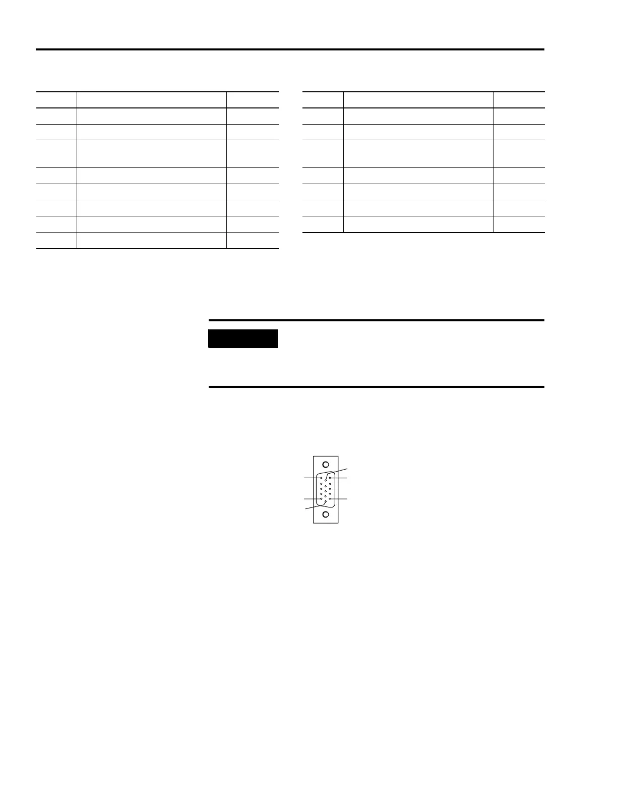
Pin Orientation for 15-pin Motor Feedback (MF) Connector
MF Pin Description Signal MF Pin Description Signal
1 Sine differential input+ S2 9 Reserved —
2 Sine differential input- S4 10 Resolver excitation R2
3 Cosine differential input+ S1 11
Motor thermal switch
(normally closed)
(1) (2)
TS
4 Cosine differential input- S3 12 Reserved —
5 Resolver excitation R1 13 Reserved —
6 Common ECOMM 14 Encoder power (+5V) EPWR_5VM
7 Encoder power (+9V) EPWR_9VM 15 Reserved —
8Reserved —
(1)
Not applicable unless motor has integrated thermal protection.
(2)
When using 1326AB (resolver-based) motors, use Low-profile Connector Kit (2090-K6CK-D15MF) that connects the filtered thermal switch (pins 16 and 17) to MF-11 and
MF-6.
IMPORTANT
To meet CE requirements, combined motor power cable length
for all axes on the same dc bus must not exceed 240 m (787 ft)
with 460V systems or 160 m (525 ft) with 230V systems.
Drive-to-motor power cables must not exceed 90 m (295.5 ft).
Pin 11
Pin 6
Pin 15
Pin 1
Pin 10
Pin 5
15-pin IAM/AM
Motor Feedback Connector

 Loading...


