Publication 2094-UM001A-EN-P — September 2006
94 Connecting the Kinetix 6000 Drive System
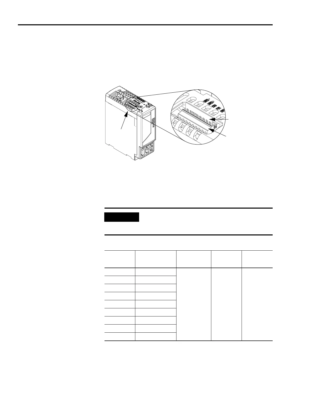
Wiring the Safe-off (SO) Connector
This example applies to any integrated axis module (IAM) or axis
module (AM) equipped with the safe-off (SO) connector.
Integrated Axis Module (CED connector)
Each IAM and AM ships with the (9-pin) wiring plug header and
motion allowed jumper installed in the safe-off connector. With the
motion allowed jumper installed, the safe-off feature is not used.
Pinouts for the safe-off (SO) connector are shown on page 52.
Safe-off (SO) Connector
To wire the safe-off connector in single axis or multi-axis
configurations, refer to the Kinetix Safe-off Feature Safety Reference
Manual, publication GMC-RM002.
1
2
3
4
5
67
8
9
1
Motion Allowed Jumper
Wiring Plug Header
Kinetix 6000 IAM/AM
(Kinetix 6000 AM is shown)
Safe-off
(SO) Connector
IMPORTANT
Pins SO-8 and -9 (24V+) are only used by the motion allowed
jumper. When wiring to the wiring plug header, the 24V supply
must come from an external source.
CED Pin Signal
Recommended
Wire Size
mm
2
(AWG)
Strip Length
mm (in.)
Torque Value
Nm (lb-in)
1FDBK2+
0.75 (18)
(stranded wire
with ferrule)
1.5 (16)
(solid wire)
7.0 (0.275) 0.235 (2.0)
2FDBK2-
3FDBK1+
4FDBK1-
5 SAFETY ENABLE2+
6 SAFETY ENABLE-
7 SAFETY ENABLE1+
824V +
924V_COM

 Loading...


