Publication 2094-UM001A-EN-P — September 2006
Troubleshooting the Kinetix 6000 Drive System 161
Changing Parameters Using the HIM
When using the HIM to monitor or change parameters, use the up and
down arrows (∧ and ∨) to arrive at selections. Refer to the
instructions that came with your HIM for more information.
Follow these steps to monitor or change parameters using the HIM.
1. Select parameter. Press
↵.
2. Select I/O AM1 Group (for IAM). Press
↵.
3. Select Analog Outputs. Press
↵.
a. Analog Output 1 is displayed. Press
↵.
b. For Analog Output 2 use arrows to select. Press
↵.
4. Press Sel.
5. Enter parameter number. Press
↵.
Using Analog Test Points to Monitor System Variables
There are two analog output test points accessible from the IOD
26-pin connector on the IAM and AM.
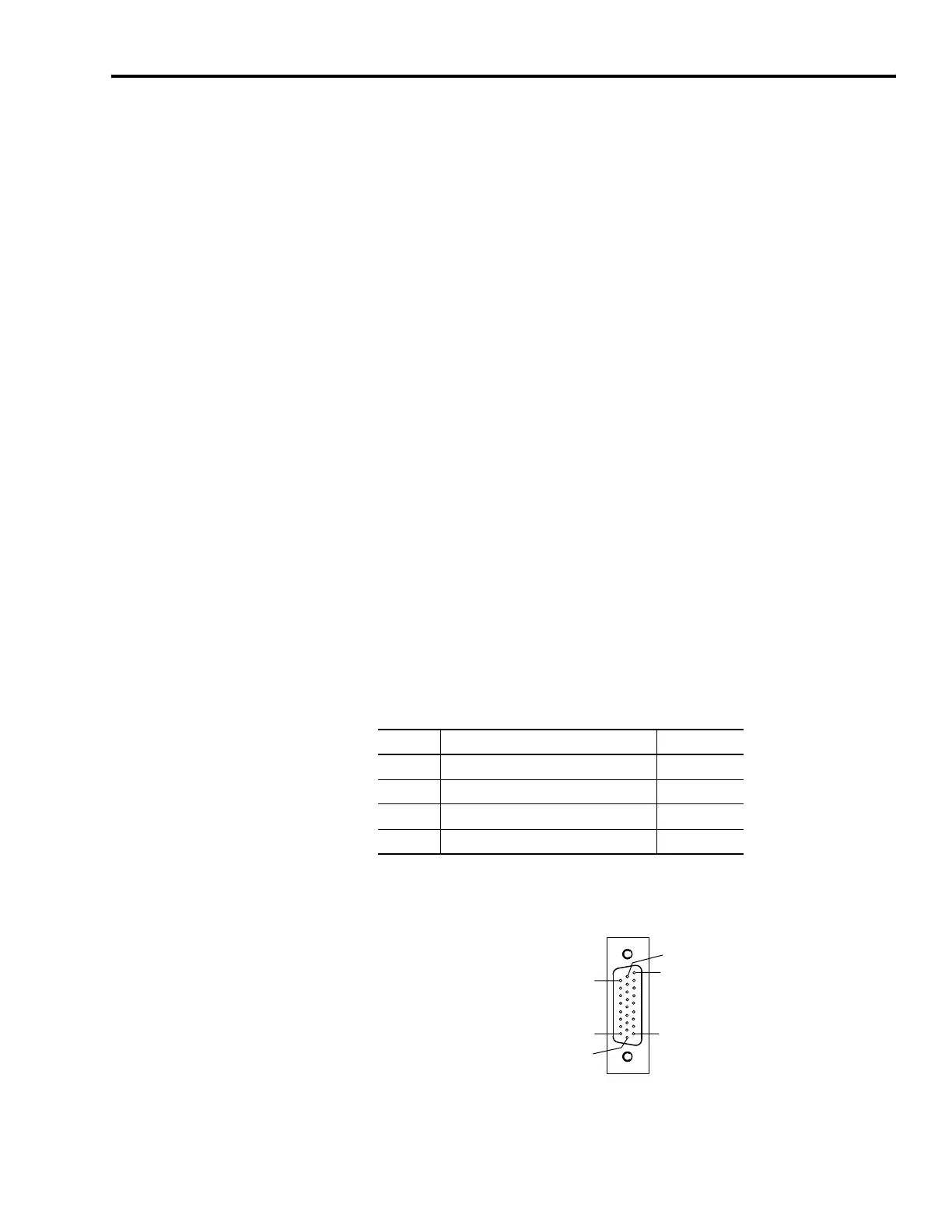
IAM/AM I/O 26-pin (IOD) Connector
Pin Orientation for 26-pin I/O (IOD) Connector
Refer to Analog Outputs on page 62 for signal specifications.
IOD Pin Description Signal
23 Analog output 0 DAC0
24 Analog output common DAC_COM
25 Analog output 1 DAC1
26 Analog output common DAC_COM
Pin 18
Pin 26
Pin 1
Pin 9
Pin 10
Pin 19
-p
n
I/O Connector

 Loading...


