Publication 2094-UM001A-EN-P — September 2006
Planning the Kinetix 6000 Drive System Installation 23
Enclosure Selection
The following example is provided to assist you in sizing an enclosure
for your Kinetix 6000 system. The example system consists of the
following components:
• 6-axis Kinetix 6000 servo drive system
• Line Interface Module (LIM)
• ControlLogix chassis and modules (controller)
Size the Kinetix 6000 servo drive and LIM and use the results to
predict the amount of heat dissipated into the enclosure. You will also
need heat dissipation data from other equipment inside the enclosure
(such as ControlLogix controller). Once the total amount of heat
dissipation (in watts) is known, the minimum enclosure size can be
calculated.
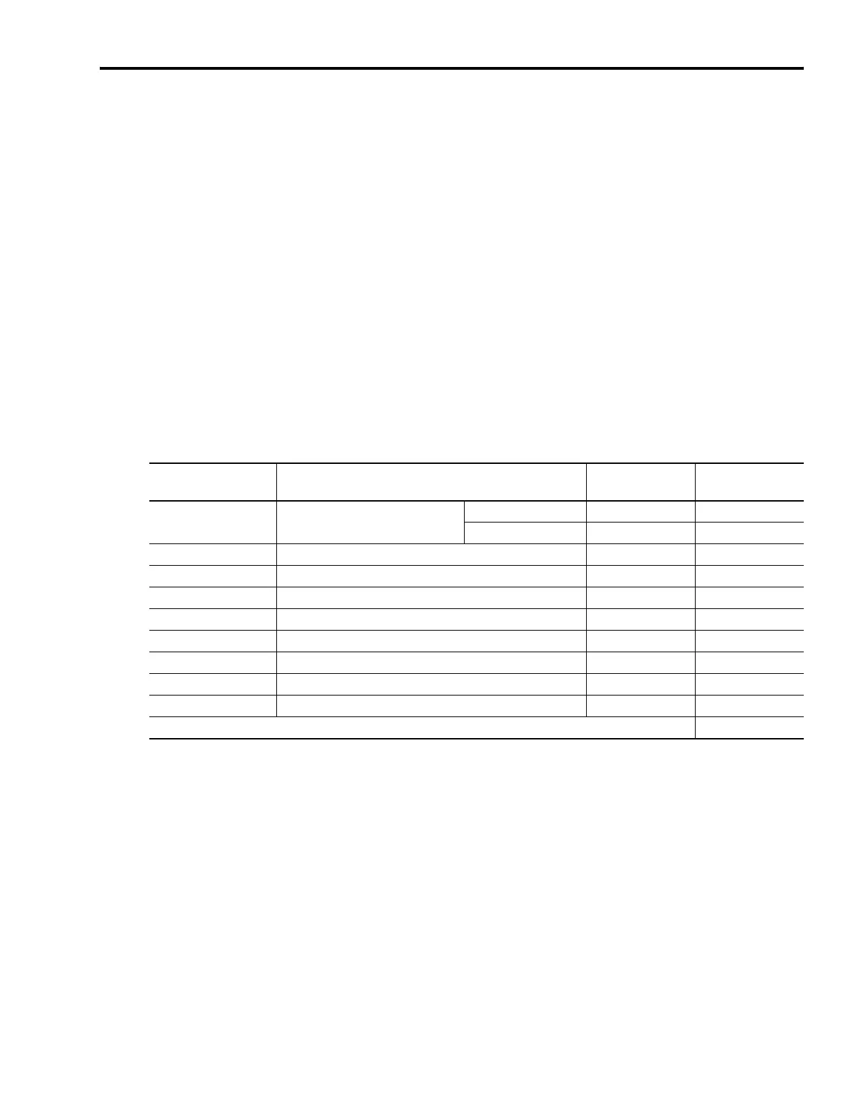
Kinetix 6000 System Heat Dissipation Example
Enclosure Component Description
Loading
(1)
Heat Dissipation
(1)
watts
2094-AC09-M02
Integrated axis module (IAM),
200/230V
6 kW (converter section) 20% 33
15A (inverter section) 40% 73
2094-AM02 Axis module (AM), 200/230V, 15 A 60% 82
2094-AM02 Axis module (AM), 200/230V, 15 A 60% 82
2094-AM01 Axis module (AM), 200/230V, 9 A 40% 69
2094-AM01 Axis module (AM), 200/230V, 9 A 40% 69
2094-AM01 Axis module (AM), 200/230V, 9 A 20% 62
2094-AL09 Line interface module (LIM), 200/230V, 6 kW, 6 A; 24V dc 3 A 100% 72
2094-PR6 Power rail, 230V, 6 axis N/A 0
2090-XB33-32 Resistive brake module (RBM), 33 A, 32 Ω N/A 30
Total Kinetix 6000 system wattage 572
(1)
To determine heat dissipation specifications for the Kinetix 6000 components, refer to Power Dissipation Specifications on page 180.

 Loading...


