Publication 2094-UM001A-EN-P — September 2006
Kinetix 6000 Connector Data 57
Auxiliary Feedback Connector Pinouts
For TTL devices, the position count will increase when A leads B. For
sinusoidal devices, the position count will increase when cosine leads
sine.
Stegmann Hiperface (SRS and SRM only)
TTL or Sine/Cosine with Index Pulse
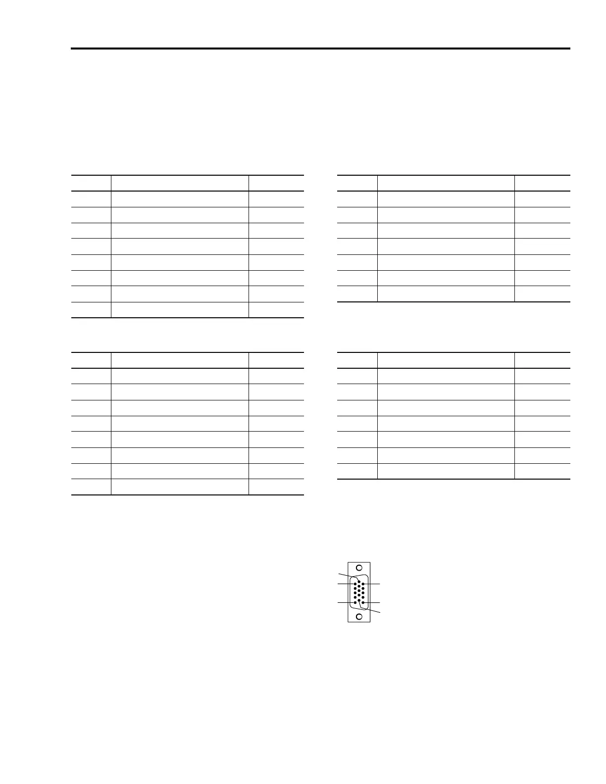
Pin Orientation for 15-pin Auxiliary Feedback (AF) Connector
AF Pin Description Signal AF Pin Description Signal
1 Sine differential input+ SINE+ 9 Reserved —
2 Sine differential input- SINE- 10 Hiperface data channel DATA-
3 Cosine differential input+ COS+ 11 Reserved —
4 Cosine differential input- COS- 12 Reserved —
5 Hiperface data channel DATA+ 13 Reserved —
6 Common ECOM 14 Encoder power (+5V) EPWR_5V
7 Encoder power (+9V) EPWR_9V 15 Reserved —
8Reserved —
AF Pin Description Signal AF Pin Description Signal
1 A+ / Sine differential input+ A+ / SINE+ 9 Reserved —
2 A- / Sine differential input- A- / SINE- 10 Index pulse- I-
3 B+ / Cosine differential input+ B+ / COS+ 11 Reserved —
4 B- / Cosine differential input- B- / COS- 12 Reserved —
5 Index pulse+ I+ 13 Reserved —
6 Common ECOM 14 Encoder power (+5V) EPWR_5V
7 Encoder power (+9V) EPWR_9V 15 Reserved —
8Reserved —
Pin 1
Pin 11
Pin 10
Pin 5
Pin 6
Pin 15
15-pin IAM/AM
Auxiliary Feedback Connector

 Loading...


