Publication 2094-UM001A-EN-P — September 2006
108 Connecting the Kinetix 6000 Drive System
Wiring Feedback and I/O
Connectors
These procedures assume you have mounted your Kinetix 6000
system, completed all power wiring, and are ready to connect your
feedback and I/O cables.
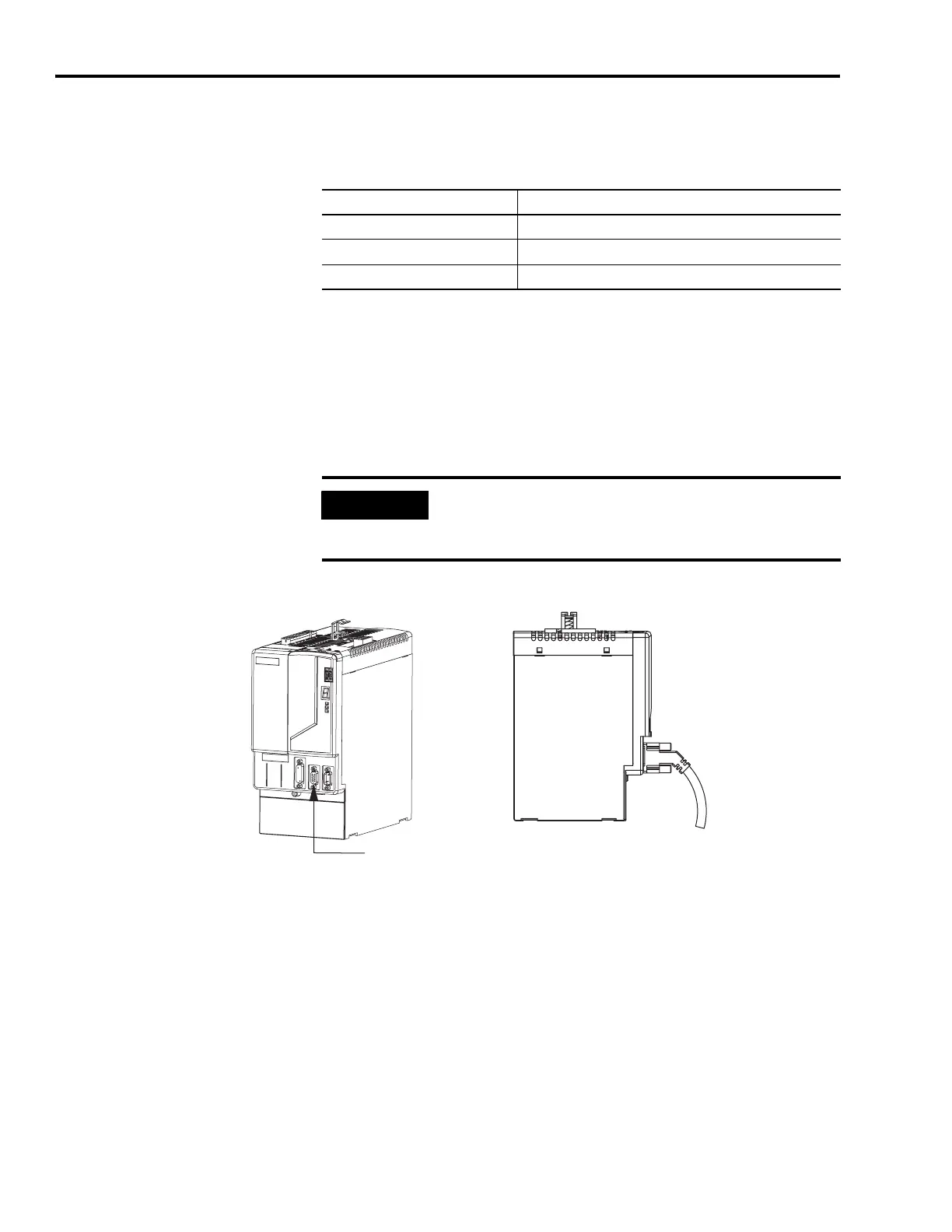
Connecting Premolded Motor Feedback Cables
Motor feedback cables with premolded connectors plug directly into
15-pin motor feedback (MF) connectors on either the IAM or AM (no
wiring is necessary).
Integrated Axis Module/Axis Module (MF connector)
For This Connection Go to
Premolded cable Connecting Premolded Motor Feedback Cables on page 108.
Panel-mounted breakout board Wiring Panel-mounted Breakout Board Kits on page 109.
Low-profile connector Wiring Low-profile Connector Kits on page 110.
IMPORTANT
When using Bulletin 2090 cables with premolded connectors,
tighten the mounting screws (finger tight) to improve system
performance.
Integrated Axis Module, Front View
(2094-BC02-M02-S is shown)
Motor Feedback (MF) Connector
Premolded Connector
(2090-UXNFBMP-S
xx
cable)
Integrated Axis Module, Side View
(2094-BC02-M02-S is shown)

 Loading...


