Publication 2094-UM001A-EN-P — September 2006
68 Kinetix 6000 Connector Data
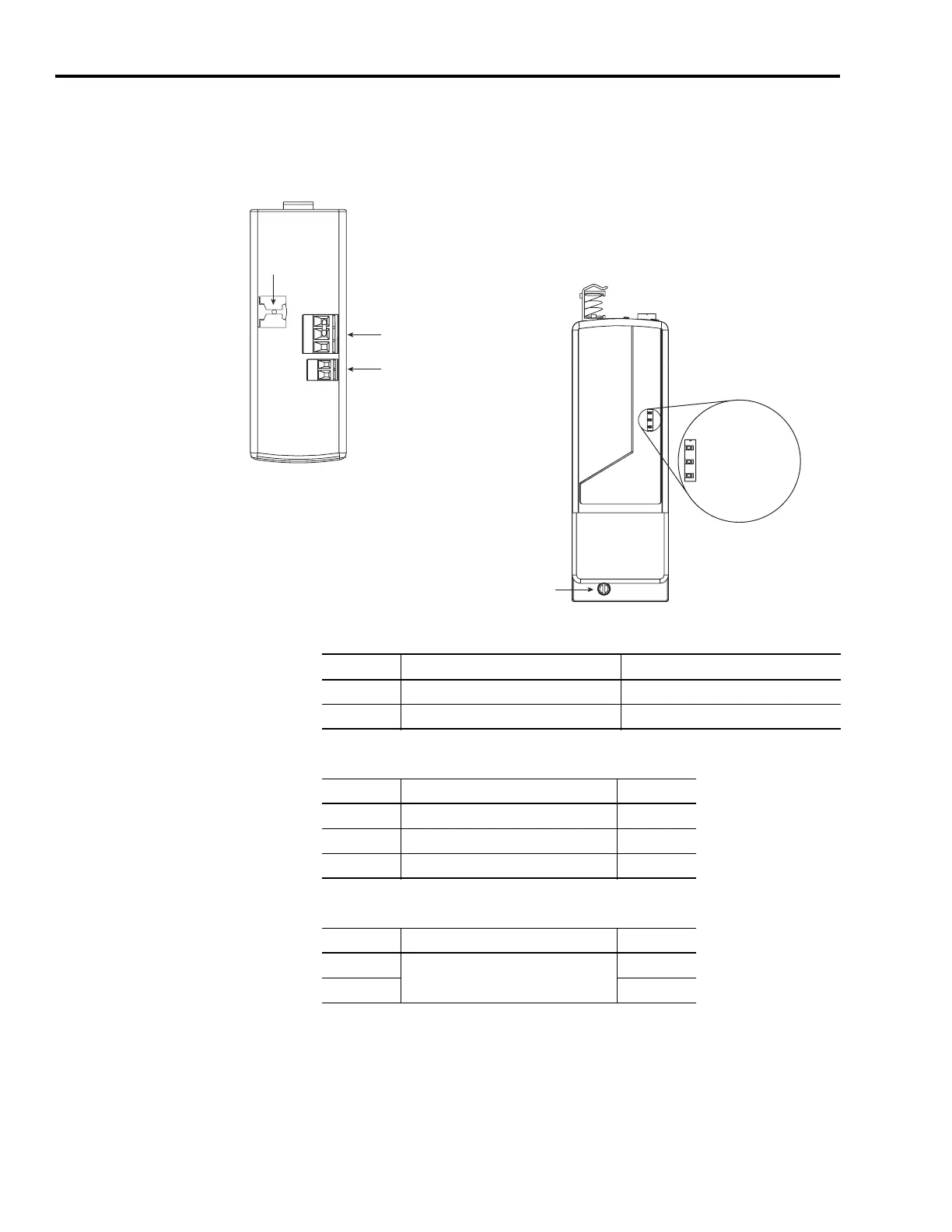
Locating Shunt Module
Connectors and Indicators
The Kinetix 6000 shunt module (2094-BSP2) is suitable for both 230V
and 460V applications.
Locating Shunt Module Connectors and Indicators
Shunt Module Connectors
External Shunt Resistor Three-pin (RC) Connector Pinout
External Thermal Switch Two-pin (TS) Connector Pinout
Refer to Understanding External Shunt Module Connections on page
113 when wiring the RC and TS connectors.
1 2 3
1 2
COL
INT
DC+
TS2
TS1
Mounting Screw
Shunt Module, Front View
(2094-BSP2)
Shunt Module, Front View
(2094-BSP2)
External Shunt Resistor
(RC) Connector
External Thermal Switch
(TS) Connector
Motor Cable
Shield Clamp
Shunt Fault LED
Over-Temp Fault LED
Bus Status LED
Designator Description Connector
RC External shunt resistor connector Three-position connector housing
TS Thermal switch connector Two-position connector housing
RC Pin Description Signal
1 External shunt resistor connection DC+
2 Internal shunt connection INT
3 Shunt collector connection COL
TS Pin Description Signal
1
External passive shunt module thermal
switch connections
TS1
2TS2

 Loading...


