Publication 2094-UM001A-EN-P — September 2006
Connecting the Kinetix 6000 Drive System 107
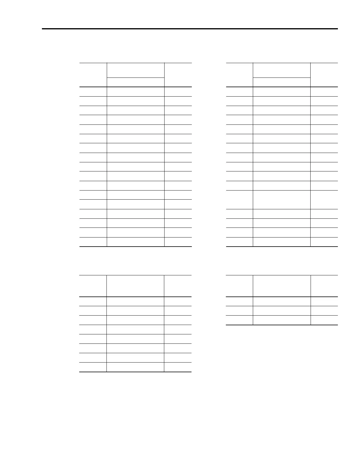
2090-XXNFHF-Sxx Feedback Cable 2090-XXNFY-Sxx Feedback Cable
Motor
Connector
Pin
Incremental Encoder
Feedback
Drive MF
Connector
Pin
Motor
Connector
Pin
Incremental Encoder
Feedback
Drive MF
Connector
Pin
F-Series Motors Y-Series Motors
AAM+ 1 9AM+ 1
B AM- 2 10 AM- 2
C BM+ 3 11 BM+ 3
D BM- 4 12 BM- 4
E IM+ 5 13 IM+ 5
F IM- 10 14 IM- 10
G Reserved – 15 S1 12
H Reserved – 17 S2 13
JEPWR_5VM 14 19S3 8
K EPWR_5VM 14 22 EPWR_5VM 14
LECOMM 6 23ECOMM 6
MECOMM 6
24 Drain
Connector
Housing
NS2 13
P S3 8 Reserved Reserved 7
R TS+ 11 Reserved Reserved 9
S TS- 6 Reserved Reserved 11
T S1 12 Reserved Reserved 15
1326-CCU-xxx Feedback Cable 1326-CPx1-xxx Power Cable
Motor
Connector
Pin
Resolver
Feedback
1326AB-Bxxxx-21
Drive MF
Connector
Pin
(1)
Motor
Connector
Pin
Thermal Switch
Connections
1326AB-Bxxxx-21
Drive MF
Connector
Pin
(2)
AR1 5 5TS+ 16
BR2 10 9TS- 17
C – – – Shield S
DS1 3
ES3 4
F– –
GS2 1
HS4 2
(1)
For termination of individual drain wires, use Low Profile connector kit (2090-K6CK-D15MF) and reference figure on page 111.
(2)
Thermal switch wires (5 and 9) are in the motor power cable (1326-CPx1-xxx). Use Low Profile connector kit (2090-K6CK-D15MF) and reference figure
on page 111.

 Loading...


