Publication 2094-UM001A-EN-P — September 2006
Connecting the Kinetix 6000 Drive System 111
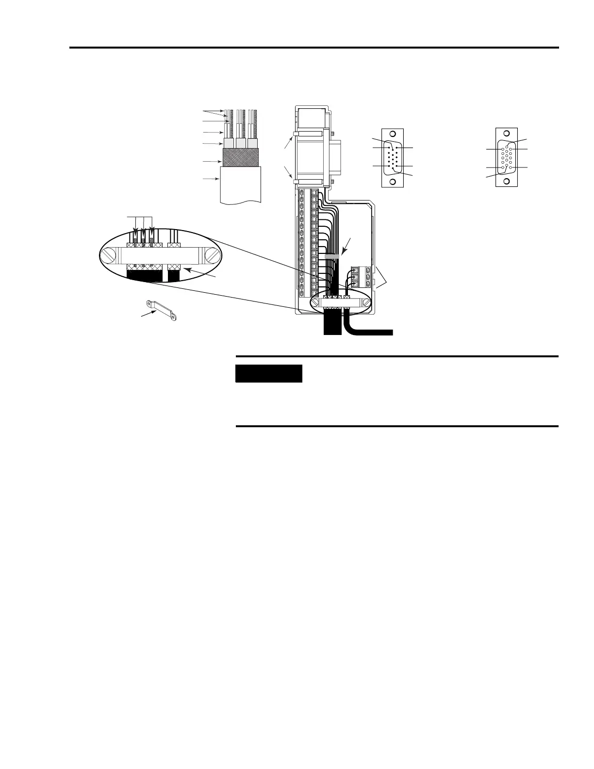
Wiring (15-Pin) Flying-lead Feedback Cable Connections
1326-CCUx-xxx Motor Feedback Cable
Pin 1
Pin 11
Pin 10
Pin 5
Pin 6
Pin 15
Pin 1
Pin 10
Pin 5
Pin 11
Pin 6
Pin 15
1
2
34
5
678
91011121314150
S16
17
15-pin (male) Motor Feedback
Low-profile Connector
15-pin (female) Auxiliary Feedback
Low-profile Connector
Refer to Chapter 4 for feedback
signal descriptions.
Refer to Wiring Examples beginning on
page 192 for the motor feedback
interconnect drawing for your application.
Pins S, 16, and 17 are only included on
2090-K6CK-D15MF Low Profile connectors and
used for thermal switch connections to 1326AB
(resolver-based) motors. After filtering, these pins
connect to MF-11 and -6.
Tie
Wrap
Exposed Braid under clamp
1326-CCUx-xxx Feedback Cable
Shield Clamp
Thermal Switch Wires
Outer Insulation
Braided Shield
Foil Shield
Wire Insulation
Drain Wire
Bare Wires
Drain wire (only with 1326-CCUx-xxx
cable) folded back under clamp.
Turn clamp over to hold
small wires secure.
Mounting
Screws
1326-CCUx-xxx
IMPORTANT
The purpose of the cable shield clamp is to provide a proper
ground and improve system performance, not stress relief.
Clamping the exposed braid under the shield clamp is critical.
Turn clamp over, if necessary, to ensure a proper ground.

 Loading...


