Publication 2094-UM001A-EN-P — September 2006
122 Configure and Startup the Kinetix 6000 Drive System
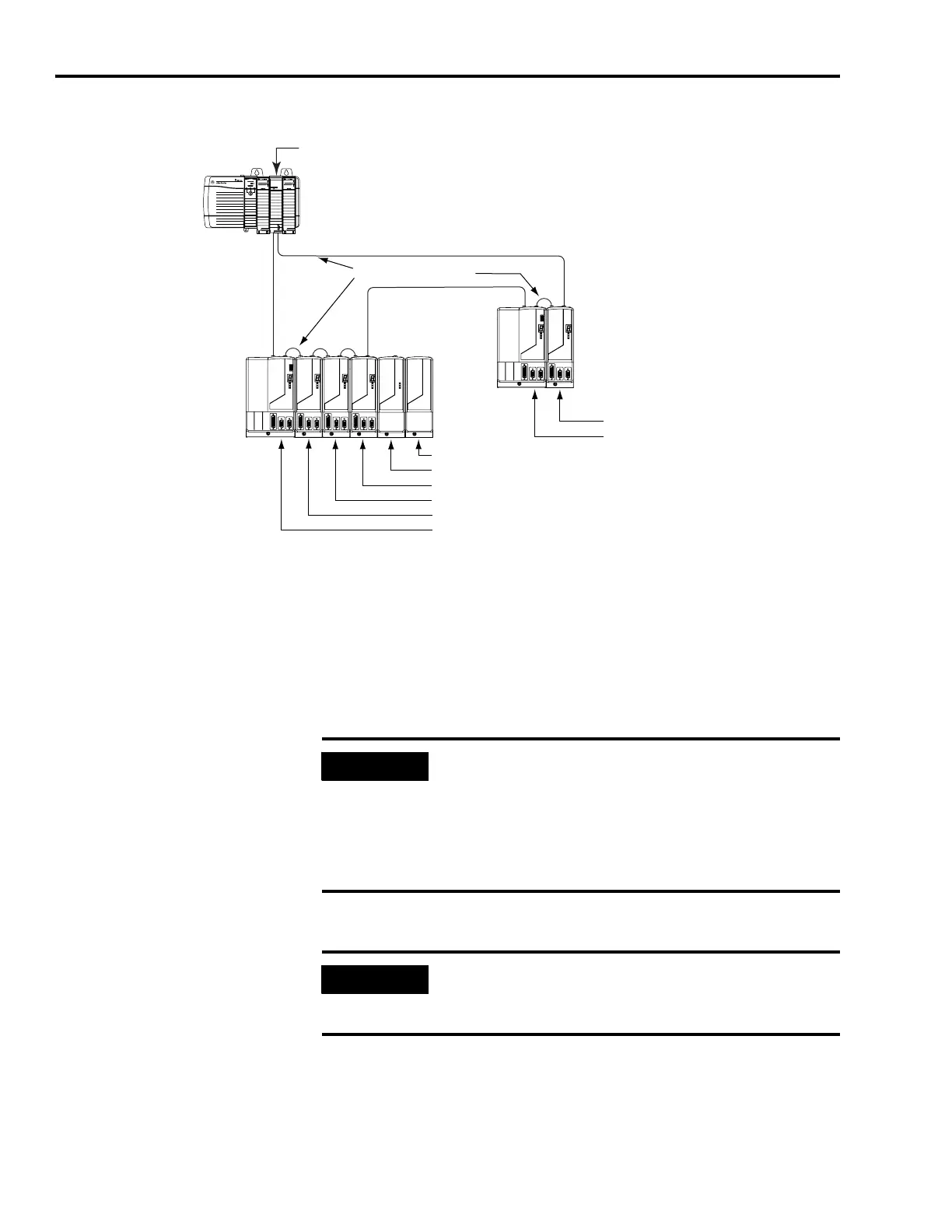
Node Addressing Example 1
In Example 1, the Kinetix 6000 (6-axis) System 1 power rail contains
one IAM, three AMs, one SM, and one slot filler module. The shunt
module and slot filler modules are assigned a node address, but they
do not use it.
Kinetix 6000 (2-axis) System 2 power rail contains one IAM and one
AM. The base node address of the IAM (system 2) must be set for an
address of ≥16 or ≤
8.
SERCOS interface
TM
Tx (rear)
Rx (front)
OK
CP
Kinetix 6000
System 2
(2-axis power rail)
15 = Slot Filler Node Address
14 = Shunt Module Node Address
13 = AM (axis 4) Node Address
12 = AM (axis 3) Node Address
11 = AM (axis 2) Node Address
10 = IAM (axis 1) Base Node Address
Logix Platform
(ControlLogix is shown)
SERCOS Fiber-optic Ring
1756-MxxSE SERCOS
interface Module
17 = AM (axis 2) Node Address
16 = IAM (axis 1) Base Node Address
Kinetix 6000
System 1
(6-axis power rail)
Receive
Receive
Transmit
Trans mit
Transmit
Receive
IMPORTANT
The node address for each axis module is determined by the
base node-address switch setting on the IAM.
Do not position axis modules to the right of shunt or slot filler
modules. The added distance between non-adjacent axes can
increase electrical noise and impedance, and requires longer
fiber-optic cable lengths.
IMPORTANT
Slot filler modules must be used to fill any unoccupied slot on
the power rail. However, the slot fillers may also be removed
and replaced by an axis or shunt module in the future.

 Loading...


