Publication 2094-UM001A-EN-P — September 2006
198 Interconnect Diagrams
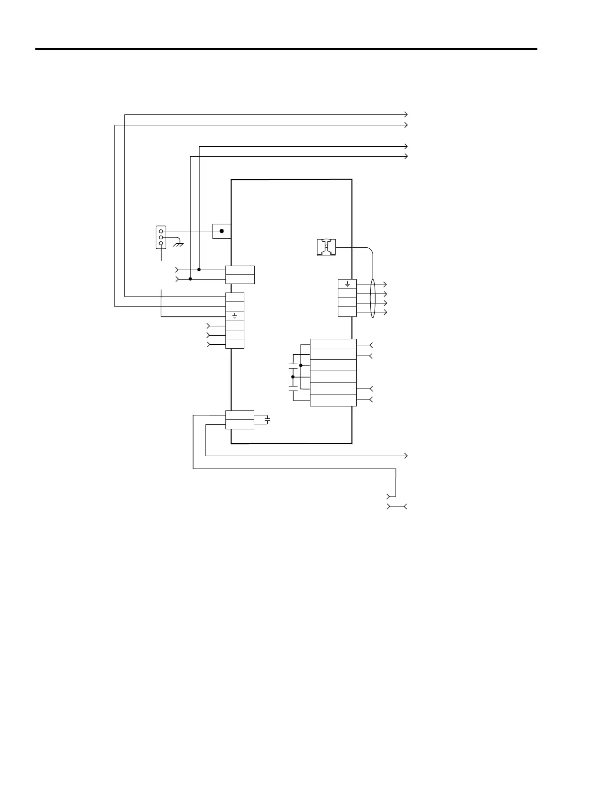
Leader IAM Wiring Example with Multiple Follower IAM
CONT EN-
CONT EN+
W
V
U
DC-
DC+
L3
L2
L1
CTRL 2
CTRL 1
1
2
1
2
3
4
5
6
1
2
6
5
4
3
2
1
4
3
2
1
MBRK -
MBRK +
COM
PWR
DBRK -
DBRK +
Note 4
Control Power
(CPD) Connector
Contactor Enable
(CED) Connector
Note 14
Motor/Resistive
Brake (BC) Connector
Three-phase
Motor Power
Connections
Note 16
Motor Power
(MP) Connector
Cable Shield
Clamp
Note 10
Kinetix 6000
Common Bus Leader IAM
2094-ACxx-Mxx or -BCxx-Mxx
Power Rail
Ground Stud
DC Bus
and
Three-phase
Input (IPD)
Connector
Single-phase Input
95...264V ac RMS
Notes 1, 2
Bonded Cabinet
Ground Bus *
To Follower
Control Circuit
Connections
To Follower
Control Power
Connections
To Follower
DC Bus Connections
Three-phase Input from LIM
or Input Power Contactor (M1)
195...264V ac RMS
or 324...528V ac RMS
Notes 1, 2, 7, 8
Wire the leader and follower IAM
contactor enable terminals in series
with the safety control string or LIM I/O.

 Loading...


