Publication 2094-UM001A-EN-P — September 2006
250 Integrating Resistive Brake Modules with Kinetix 6000 Drives
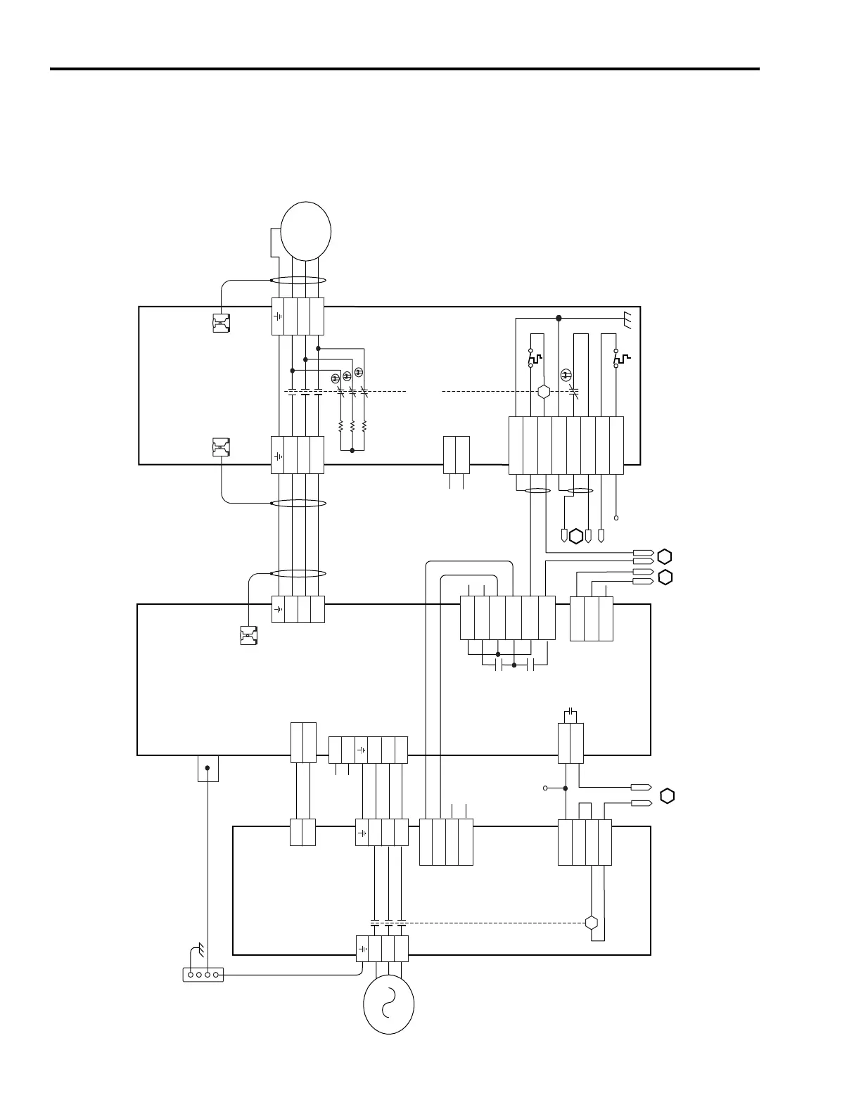
The example diagram below shows Kinetix 6000 IAM and LIM
(2094-AL09 and -BL02) wired with the Bulletin 2090 RBM in a
category 3 configuration.
RBM Wiring Example (Category 3 Configuration per EN954-1)
T2
T1
K
4
3
2
1
4
3
2
1
D
C
B
A
IO_PWR
BRKTMP0
CONT EN-
CONT EN+
W
V
U
L3
L2
L1
24-26
20-22
13
4
DC-
DC+
L3
L2
L1
L1
L2
CTRL 1
CTRL 2
L3'
L2'
L1'
1
2
1
2
3
4
5
6
1
2
6
5
4
3
2
1
4
3
2
1
MBRK_PWR
MBRK_COM
MBRK_PWR
MBRK_COM
W_DRIVE
V_DRIVE
U_DRIVE
W_MTR
V_MTR
U_MTR
SHIELD
COIL_A2
COIL_A1
SHIELD
CONSTANT_42
CONSTANT_41
TS_22
TS_21
MBRK -
MBRK +
COM
PWR
DBRK -
DBRK +
8
7
6
5
4
3
2
1
K
IO_PWR
IO_COM
COIL_A1
COIL_A2
BRKSTAT0
IO_PWR
L1
L2
L3
AUX3
AUX2
AUX1
R3
R2
R1
W
V
U
GND
M
AUX4
1
2
3
4
2
1
1
2
3
+24V_PWR
ENABLE
+24V_COM
A
B
C
D
2
1
L2
L1
Note 1
Note 4
Note 1
Auxiliary 230V ac
Input (TB4) Connector
(2090-XB120-xx only)
Kinetix 6000
Integrated Axis Module
2094-ACxx-Mxx or -BCxx-Mxx
(Axis_0)
Cable Shield
Clamp
2090-XXNRB-14F0P7
RBM to Drive Interface Cable
Note 2
Motor Connections
(TB2) Connector
Drive Connections
(TB1) Connector
I/O Connections
(TB3) Connector
Motor/Resistive
Brake (BC) Connector
Motor Power
(MP) Connector
Cable Shield
Clamp
Cable Shield
Clamp
Motor Power
Connections
Bulletin 2090
Resistive Brake Module
2090-XBxx-xx
(RBM_0)
Contactor Enable
(CED) Connector
Note 1
Note 3
Control Power
(CPD) Connector
Power Rail
Ground Stud
DC Bus
and
Three-phase
Input (IPD)
Connector
24V dc Output
(PSL) Connector
Three-phase Input
(IPL) Connector
I/O (IOL)
Connector
Three-phase Output
(OPL) Connector
Single-Phase Output
(CPL) Connector
Bonded Cabinet
Ground Bus*
* Indicates User Supplied Component
Kinetix 6000
Line Interface Module
2094-AL09 and -BL02
I/O (IOD)
Connector
Note 6
Refer to the wiring examples in
Appendix B for motor power
cable catalog numbers.
Note 2

 Loading...


