Publication 2094-UM001A-EN-P — September 2006
Planning the Kinetix 6000 Drive System Installation 33
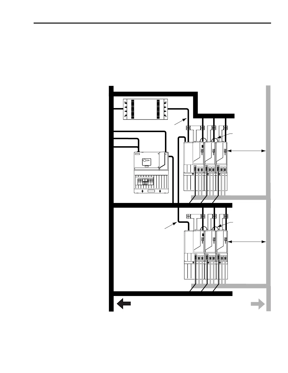
Observe the following guidelines when a LIM (2094-ALxxS, -BLxxS, or
-XL75S-Cx) is used in a dc common bus configuration and the
follower IAM is mounted below the leader IAM:
Keep the dc common bus cable (very dirty) segregated from all other
cables (not in a wireway).
Establishing Noise Zones (dc common bus)
(1)
If IAM/AM I/O cable contains (dirty) relay wires, route cable with LIM I/O cable in dirty wireway.
(2)
When space does not permit the 150 mm (6.0 in.) segregation, use a grounded steel shield instead. For
examples, refer to the System Design for Control of Electrical Noise Reference Manual, publication
GMC-RM001.
C
D
VD
D
D
D
VD
D
C
VD
D
D
D
D
D
D
MAIN VAC
Line Interface Module
Kinetix 6000 System
(leader IAM)
Dirty Wireway
Clean Wireway
I/O
(1)
and Feedback Cables
Motor Power Cables
Fiber-optic Cable
VAC Line, AUX VAC Output, 24V
VAC Line
AC Line Filter
VAC Load
I/O
(1)
and Feedback Cables
Fiber-optic Cable
Kinetix 6000 System
(follower IAM)
Very Dirty Filter/IAM Connections
Segregated (not in wireway)
Very Dirty DC Bus Connections
Segregated (not in wireway)
No sensitive
equipment within
150 mm (6.0 in.).
(2)
Route 24V dc I/O
shielded cable.
Route encoder/analog/registration
shielded cables.
No sensitive
equipment within
150 mm (6.0 in.).
(2)

 Loading...


