Publication 2094-UM001A-EN-P — September 2006
38 Planning the Kinetix 6000 Drive System Installation
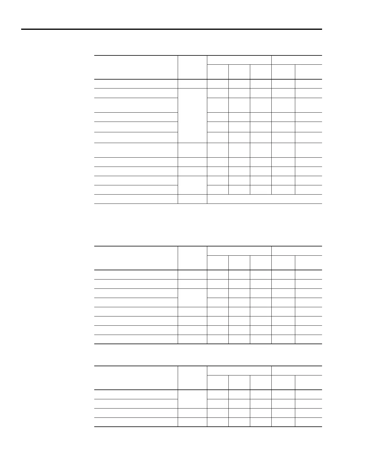
Integrated Axis Module or Axis Module (inverter side)
Line Interface Module
External Shunt Resistor Kit
Wire/Cable Connector
Zone Method
Very
Dirty
Dirty Clean
Ferrite
Sleeve
Shielded
Cable
U, V, W (motor power) MP X X
MBRK-, MBRK+ (motor brake)
BC
X
MBRK-, MBRK+ (motor brake)
1326AB motors with resolver feedback
XX
DBRK-, DBRK+ (resistive brake) X
COM, PWR (24V dc), filtered
(1)
X
COM, PWR (24V dc), unfiltered
(2)
X
COM, PWR (24V dc), safety enable, and
feedback signals for safe-off feature
SO X
Motor feedback MF X X
Auxiliary feedback AF X X
Registration and analog outputs
IOD
XX
Others X
Fiber-optic Rx and Tx No Restrictions
(1)
This is a clean 24V dc available for any device that may require it.
(2)
This is a dirty 24V dc available for motor brakes and contactors.
Wire/Cable Connector
Zone Method
Very
Dirty
Dirty Clean
Ferrite
Sleeve
Shielded
Cable
VAC line (main input) IPL X
230V ac input APL X
VAC load (shielded option)
OPL
XX
VAC load (unshielded option) X
Control power output CPL X
MBRK PWR, MBRK COM P1L/PSL X
Status I/O IOL X
Auxiliary 230V ac P2L X
Wire/Cable Connector
Zone Method
Very
Dirty
Dirty Clean
Ferrite
Sleeve
Shielded
Cable
COL, DC+ (shielded option)
RC
XX
COL, DC+ (unshielded option) X
Thermal switch TS X X
Fan (if present) N/A X

 Loading...


