Publication 2094-UM001A-EN-P — September 2006
Kinetix 6000 Connector Data 51
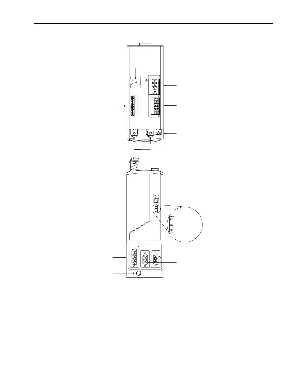
Axis Module Connectors and Indicators
BAUD
RATE
TX
RX
W
V
U
MBRK -
MBRK +
COM
PWR
DBRK -
DBRK +
1 2 3 4
1 2 3 4 5 6
1 2 3 4 5 6 7 8 9
Motor Power
(MP) Connector
Motor/Resistive Brake
(BC) Connector
SERCOS Transmit (Tx) Connector
SERCOS Receive (Rx) Connector
Axis Module, Top View
(2094-AMP5-S is shown)
Axis Module, Front View
(2094-AMP5 is shown)
Drive Status LED
COMM Status LED
Bus Status LED
Auxiliary Feedback (AF) Connector
Motor Feedback (MF) Connector
I/O (IOD) Connector
Mounting Screw
Seven-segment
Fault Status LED
Motor Cable
Shield Clamp
SERCOS Baud Rate
and Optical Power Switches
Safe-off
(SO) Connector
(present only on the 2094-xMxx-S)

 Loading...


