Publication 2094-UM001A-EN-P — September 2006
Kinetix 6000 Connector Data 53
Headers in this table extend the safe-off (SO) connector signals for use
in wiring single and multiple safe-off drive configurations, or to
jumper around (not use) the safe-off feature.
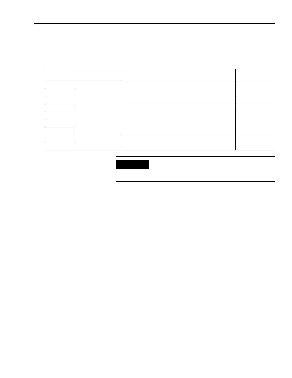
IAM/AM Safe-off 9-pin (SO) Connector
Refer to the Kinetix Safe-off Feature Safety Reference Manual,
publication GMC-RM002, for more information on safe-off headers.
Safe-off (SO)
Connector Pin
Also Applies to These
SO Connector Headers
Description Signal
1
• Wiring plug header
• First-drive wiring header
(2090-XNSM-W)
One side of the normally-closed monitoring contact of relay 2 FDBK2+
2 Other side of the normally-closed monitoring contact of relay 2 FDBK2-
3 One side of the normally-closed monitoring contact of relay 1 FDBK1+
4 Other side of the normally-closed monitoring contact of relay 1 FDBK1-
5 Coil of safety-relay 2 SAFETY ENABLE2+
6 Return for safety-relay coil power (both relays) SAFETY ENABLE-
7 Coil of safety relay 1 SAFETY ENABLE1+
8
• Wiring plug header
• Motion allowed jumper
Power for continuous enable of the safety function, 500 mA max 24V+
9 Power return used for continuous enable of safety function 24V_COM
IMPORTANT
Pins SO-8 and -9 (24V+) are only used by the motion allowed
jumper. When wiring to the wiring plug header, the 24V supply
must come from an external source.

 Loading...


