Publication 2094-UM001A-EN-P — September 2006
Connecting the Kinetix 6000 Drive System 77
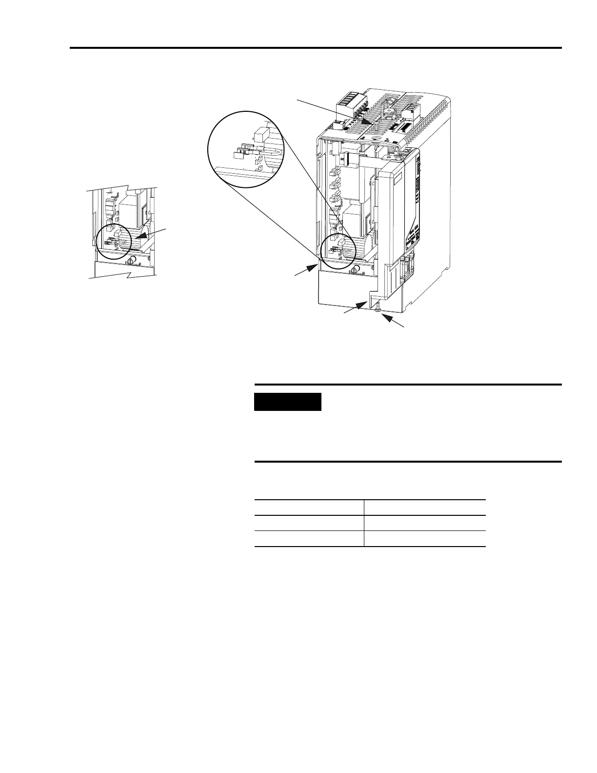
Setting the Ground Jumper (460V IAM)
2. Swing the front panel open to the right, as shown, and locate the
ground jumper.
3. Determine if you have a 230V system or 460V system.
4. Replace the IAM front panel and two screws.
Apply 1.6 Nm (14 lb-in) torque.
5. Mount the IAM back on the power rail.
Refer to Mounting the Modules on page 45 for instructions.
P13
P14
P12
Integrated Axis Module (460V)
2094-BCxx-Mxx-S
Bottom Screw
Front Panel (opened)
Ground jumper set
for grounded configuration
(default setting)
Ground jumper set
for ungrounded configuration.
Top Screw
IMPORTANT
Do not attempt to remove the front panel from the IAM.
The front panel LEDs and switches are also connected to
the IAM with a ribbon cable. The ribbon cable will act like
a hinge and allow you to swing the front panel open and
access the ground jumper.
For This IAM Move the Ground Jumper From
2094-ACxx-Mxx-S (230V) P16 to P17
2094-BCxx-Mxx-S (460V) P14 to P12

 Loading...


