Publication 2094-UM001A-EN-P — September 2006
Connecting the Kinetix 6000 Drive System 97
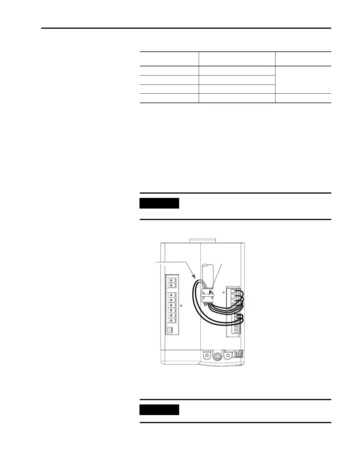
Motor Power Cables with Three-phase and Brake Wires
These MP-Series brake wires have a shield braid (shown below as
gray) that folds back under the cable clamp before the conductors are
attached to the motor brake (BC) connector. Y-Series brake wires are
not shielded and do not require routing under the cable clamp.
The thermal switch wires for the MP-Series motors are included in the
feedback cable.
Refer to Axis Module/Motor Wiring Examples beginning on page 204
for interconnect diagrams.
Motor Power Terminations (three-phase and brake wires)
The cable shield clamp shown above is mounted to an IAM. Cables
attach to the clamp on each AM in the same way.
Motor Motor Catalog Number
Motor Power Cable
Catalog Number
MP-Series Low Inertia MPL-A/B15xxx and MPL-A/B2xxx V/E
2090-XXNPMF-xxSxxMP-Series Food Grade MPF-A/BxxxxS/M
MP-Series Stainless Steel MPS-A/BxxxxS/M
Y-Series Y-xxxx 2090-XXNPY-16Sxx
IMPORTANT
No drive-end preparation is required for these cables.
Refer to page 99 for drive-end cable pinouts.
BAUD
RATE
TX
RX
DPI
DC-
DC+
L3
L2
L1
CONT EN-
CONT EN+
CTRL 2
CTRL 1
W
V
U
MBRK -
MBRK +
COM
PWR
DBRK -
DBRK +
1 2 3 4
1 2 3 4 5 6
Resistive/Motor Brake
(BC) Connector
Motor Power
(MP) Connector
Motor Cable
Shield Clamp
(with tie wrap)
MP-Series Cable Brake Wires
Y-Series brake wires are not
shielded and do not require
routing under the cable clamp.
IMPORTANT
Securing the cable shield in the clamp with a tie wrap is
recommended to improve stress relief.

 Loading...


