Rockwell Automation Publication 20P-TG002B-EN-P - February 2018 49
Part Replacement Procedures Chapter 3
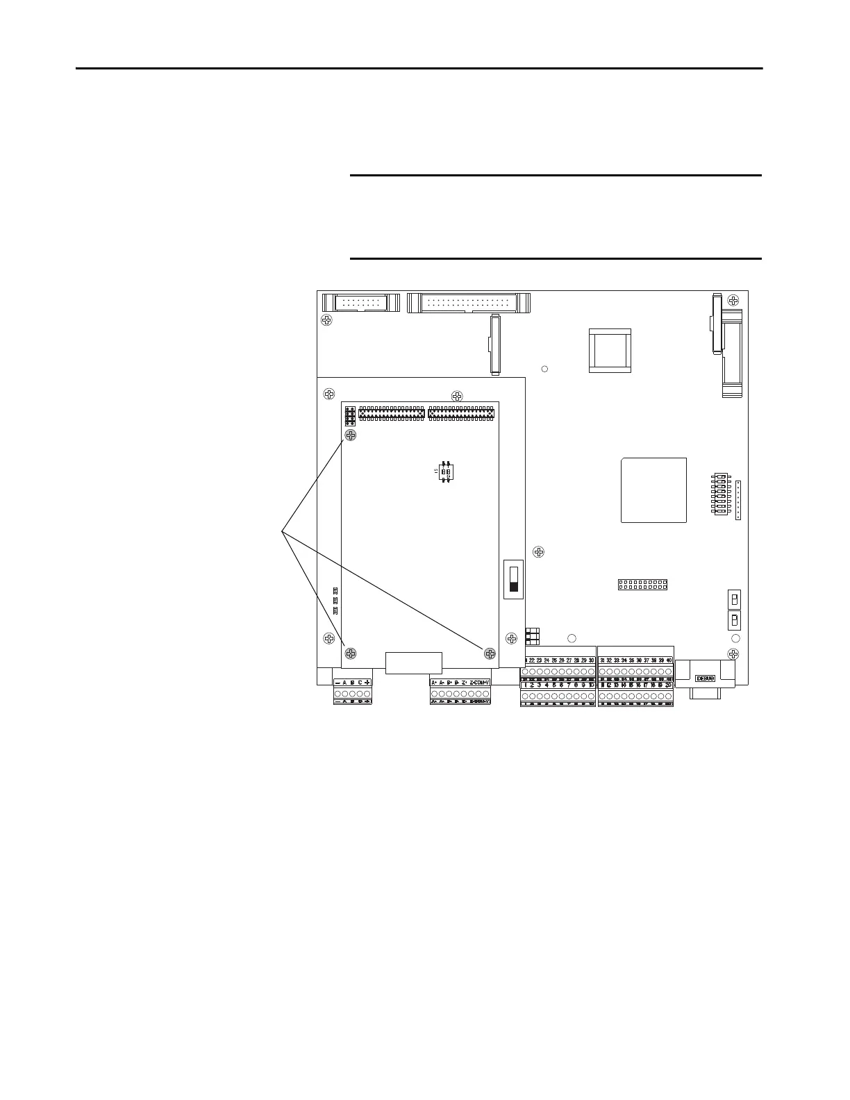
5. Remove the three hexalobular screws that secure the resolver feedback
board to the stand-offs on the resolver interface board and carefully
remove the resolver feedback board.
IMPORTANT The resolver feedback board is connected to the resolver interface
board below it via stacker connector pins at connectors P2 and P3.
Lift the resolver feedback board straight up during removal to avoid
any damage to the connector pins.
S15
XR
XA
XP3
XRE
XFCD
S21
S4
J1 J2
P1
S1
TB1 TB2
P4
P2 P3
P1
5
Tightening torque for re-
assembly is
0.7 N•m (6.2 lb•in)

 Loading...


