82 Rockwell Automation Publication 20P-TG002B-EN-P - February 2018
Chapter 3 Part Replacement Procedures
7. Remove the bus bars in order to access the SCR modules in the drive:
• For a regenerative drive, see Remove the Bus Bars from a
Regenerative Drive on page 82
.
• For a non-regenerative drive, see Remove the Bus Bars from a Non-
Regenerative Drive on page 85
.
Remove the Bus Bars from a Regenerative Drive
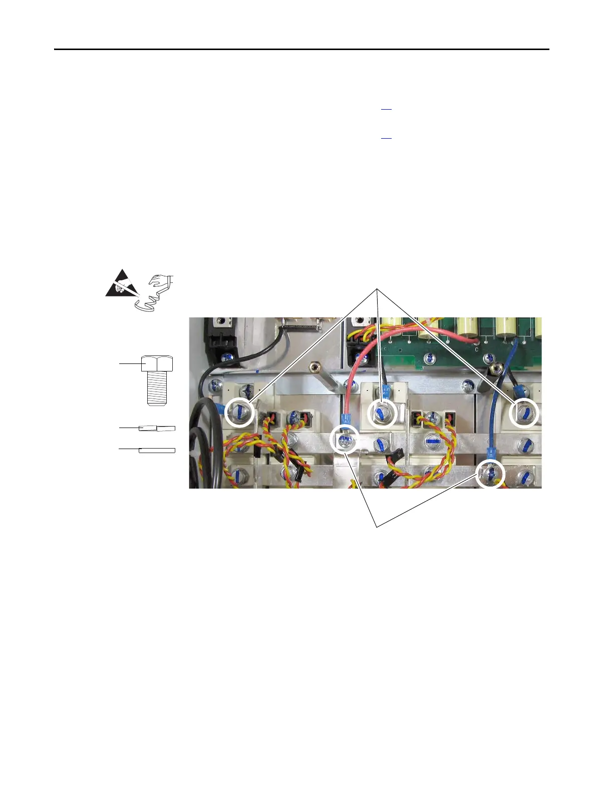
8. Remove the two screws or bolts and washers that secure the (red and
blue) wires from the AC line snubber board to the terminal bus bars (C
and D) and remove the wires.
9. Remove the three bolts and washers that secure the (black) wires from
the resistors to the terminal bus bars (U, V, and W) and remove the
wires.
=
9
8
Bolt
Lock washer
Flat washer
Note proper order of washers for
installation.
Regenerative Drive

 Loading...


