Specifications A-3
Bulletin 280G/281G, Continued
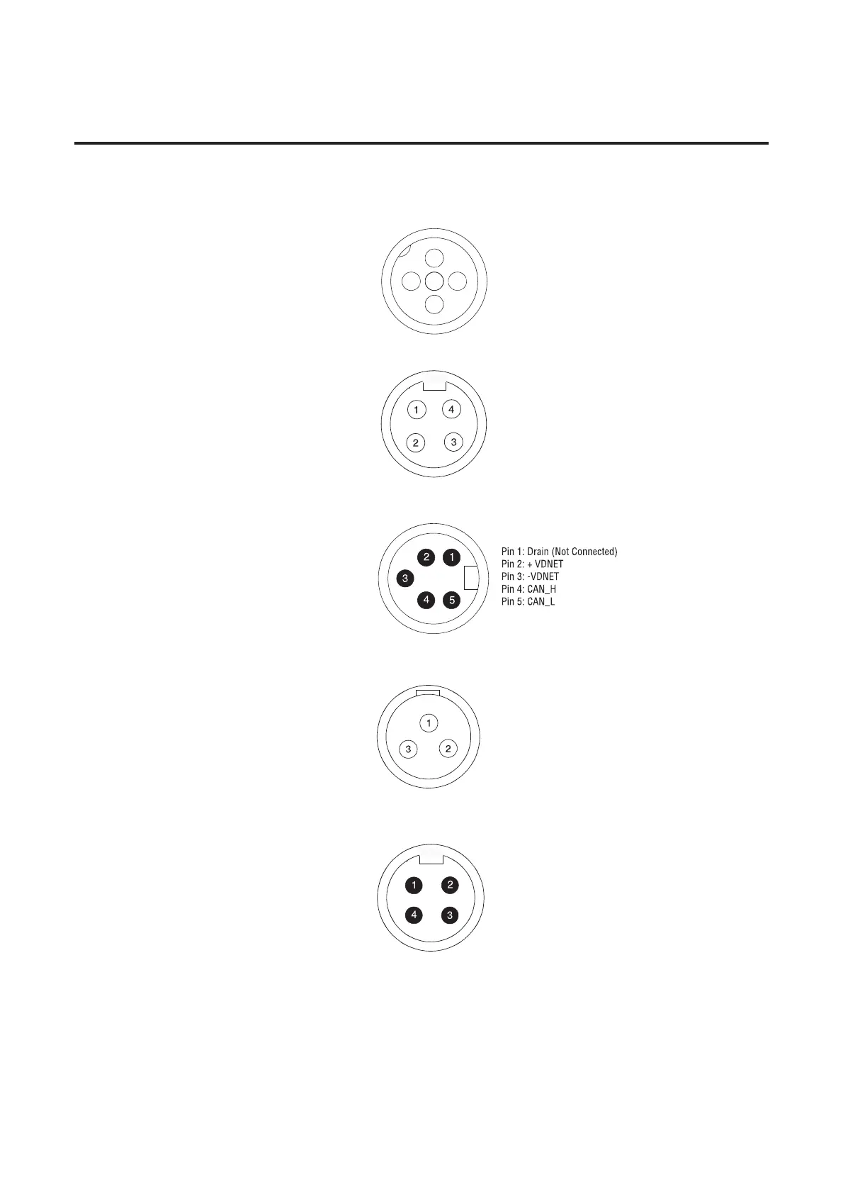
Figure A.1 External Connections for Input Connector
Figure A.2 External Connections for Motor Connector @ 460V AC
Figure A.3 External Connections for DeviceNet™ Connector
Figure A.4 External Connections for Control Brake Connector
Figure A.5 External Connections for Three-Phase Power Input
Pin 1: +V Out
Pin 2: Input
Pin 3: Comm
Pin 4: Input
Pin 5: NC (No Connection)
Pin 1: T1 - Black
Pin 2: Ground - Green/Yellow
Pin 3: T3 - Red
Pin 4: T2 - White
Pin 1: L1 - Black
Pin 2: Ground - Green/Yellow
Pin 3: L3 - Red
Pin 4: L2 - White
2
3
5
4
1
Pin 1: GND - Green/Yellow
Pin 2: L1 - Black
Pin 3: L2 - White

 Loading...


