A-8 Specifications
Bulletin 284G, Continued
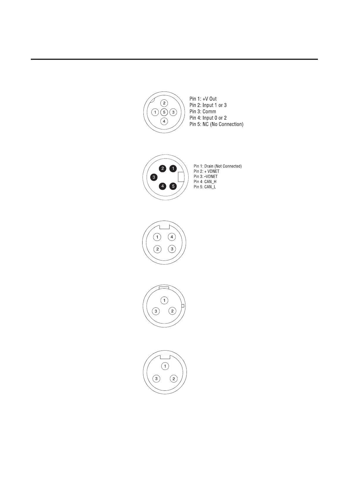
Figure A.10 External Connections for Input Connector
Figure A.11 External Connections for DeviceNet™ Connector
Figure A.12 External Connections for Motor Connector
Figure A.13 External Connections for Control Brake Connector
Figure A.14 External Connections for Dynamic Brake Connector
Pin 1: T1 - Black
Pin 2: Ground - Green/Yellow
Pin 3: T3 - Red
Pin 4: T2 - White
Pin 1: GND - Green/Yellow
Pin 2: L1 - Black
Pin 3: L2 - White
Pin 1: GND - Green/Yellow
Pin 2: BR+ - Black
Pin 3: BR- - White

 Loading...


