d04924.fm
INSTALLATION MANUAL
BRP-Powertrain
Effectivity: 912 Series
Edition 2/Rev. 0
75-00-00
page 12
August 01/2012
Coolant exit
temperature
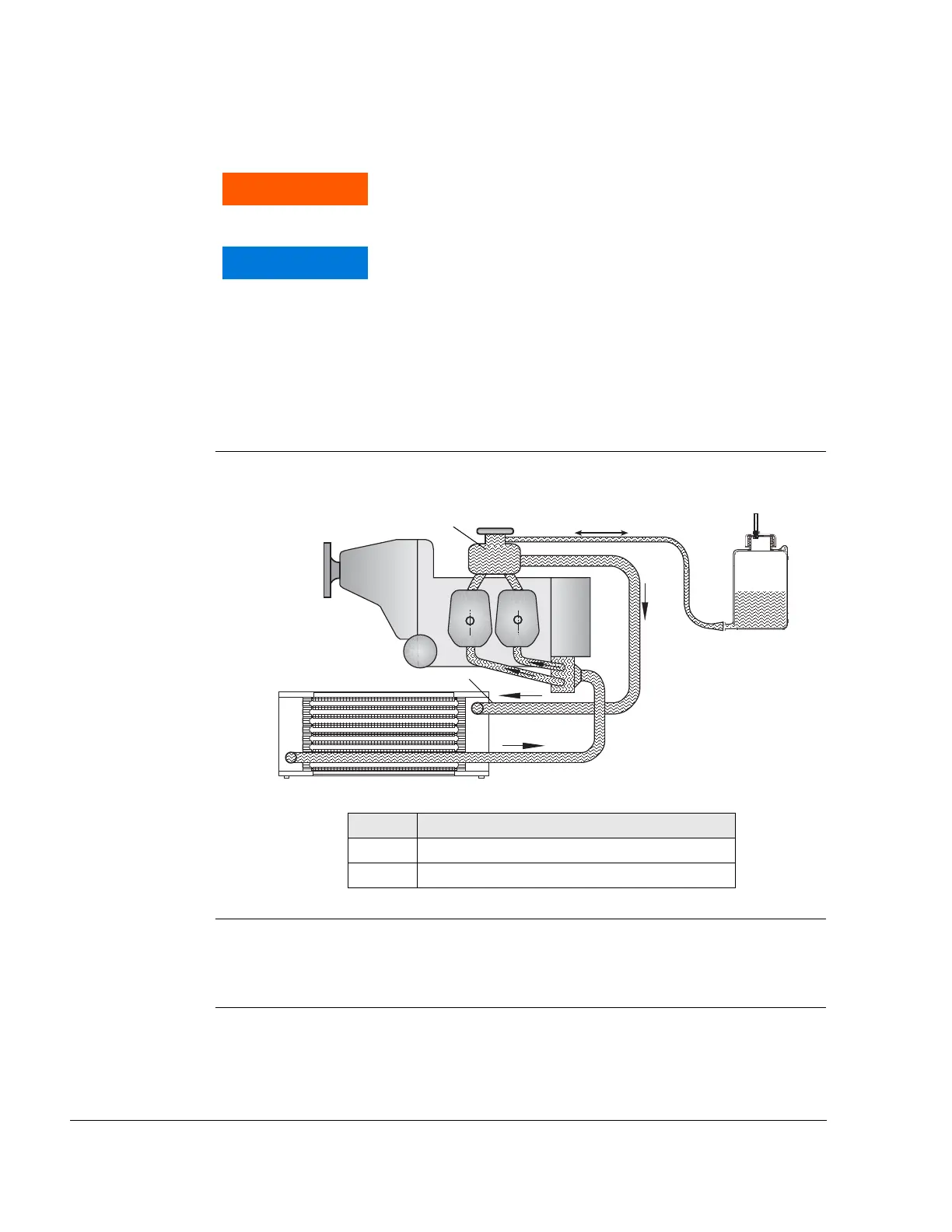
See Fig. 5.
The measuring of the coolant exit temperature is performed using a sepa-
rate sensor, which has to be installed in the line between expansion tank
(1) and radiator inlet (2).
Graphic Measurement of cylinder head temperature and coolant exit temperature
Fig. 5
09152
Installation The sensor may be installed in a “TEE“ inline with the fluid hose or the
expansion tank may be modified to attach the sensor (not supplied by
BRP-Powertrain).
Non-compliance can result in serious injuries or death!
Do not restrict the coolant flow with the sensor.
It is possible to record a false measurement when
measuring fluid temperatures. If fluid volume is lost
and the sensor is not fully submerged in the liquid, the
indicating instrument could incorrectly display a lower
temperature, by measuring the air temperature instead
of the coolant temperature.
Part Function
1 Expansion tank
2 Radiator inlet

 Loading...


