EasyManuals Logo

Rotax 912 Series Installation Manual

Rotax 912 Series
199 pages
To Next Page IconTo Next Page
To Previous Page IconTo Previous Page
Page #128 background imageLoading...
Page #128 background image
d04924.fm
INSTALLATION MANUAL
BRP-Powertrain
Effectivity: 912 Series
Edition 2/Rev. 0
75-00-00
page 18
August 01/2012
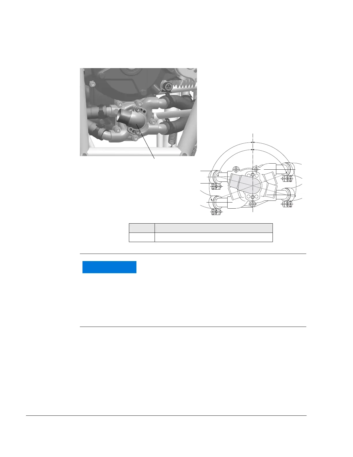
Connecting dimension
Fig. 8 08788,05536
Water inlet el-
bow
NOTE: Choose between six possible installation positions of water
inlet elbow (5) appropriate to specific installation (see illus-
tration).
Use two M6x20 Allen screws and lock washers to attach
the water inlet elbow. Tighten screws to 10 Nm (90 in.lb.).
Part Function
5 Water inlet elbow
110°
105°
70°
75°
5
WARNUNG
NOTICE
Utilize total slip-on length for the water inlet elbow and
expansion tank. Secure hoses with suitable spring or
screw clamp.

Table of Contents

Other manuals for Rotax 912 Series

Questions and Answers:

Question and Answer IconNeed help?

Do you have a question about the Rotax 912 Series and is the answer not in the manual?

Rotax 912 Series Specifications

General IconGeneral
Redline5800 rpm
TBO2000 hours
Displacement1211 cc
Bore79.5 mm
Stroke61 mm
Power Output80 hp (59.6 kW)
Compression Ratio9.0:1
Fuel TypeAvgas 100LL
Ignition SystemDual electronic ignition
Fuel SystemFuel Injected
Oil SystemDry sump
Engine Type4-cylinder, horizontally opposed, 4-stroke

Related product manuals