d04928.fm
INSTALLATION MANUAL
BRP-Powertrain
Effectivity: 912 Series
Edition 2/Rev. 0
80-00-00
page 3
August 01/2012
1) Electric starter
General note
1.1) Power supply wires from starter relay to the electric starter
Cross section At least 16 mm
2
(2.48 in
2
).
Output 0.7 kW (0.9 kW optional)
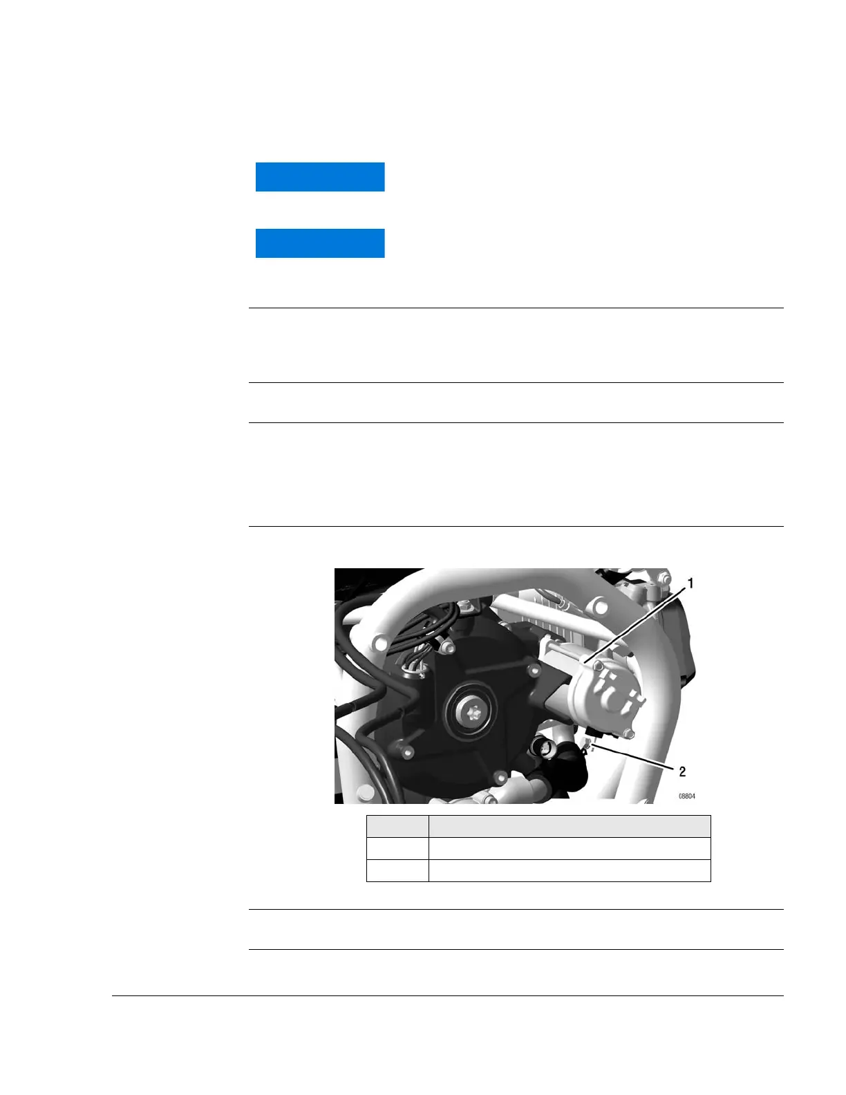
Connection See Fig. 2.
Plus terminal (2): M6 screw connection (tightening torque 4 Nm (36 in.lb))
suitable for cable terminals according to DIN 46225 (MIL-T7928; PIDG or
equivalent).
Graphic Connection
Fig. 2 00545
Grounding Grounding cable via engine block.
Suitable for short starting periods only.
Max. 80 °C (176 °F) ambient temperature by the elec-
tric starter housing. Activate starter for max. 10 sec.
(without interruption), followed by a cooling period of
2 minutes!
Part Function
1 Electric starter
2 Plus terminal

 Loading...


