88
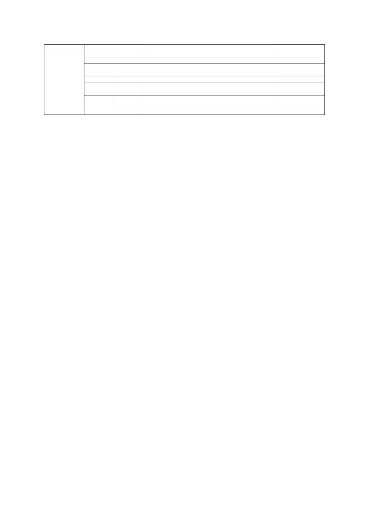
Format Code Value Description Notes
RO 00100000B
AI ±1 mA 01010000B
AI 0-20 mA 01010001B
AI 4-20 mA 01010010B
AI 0-1 mA 01010011B
AO ±1 mA 01100000B
AO 0-20 mA 01100001B
AO 4-20 mA 01100010B
AO 0-1 mA 01100011B
Empty slot
1111
××××B
NOTES:
1
Voltage Waveforms
When the 4LN3, 4LL3, 3LN3, 3LL3, 3BLN3 or 3BLL3 wiring mode is selected, the voltage waveforms will be line-to-neutral; for
any other wiring mode, they will be line-to-line.
2
Analog Outputs
1) For bi-directional analog output (
±1 mA), the zero scale setup corresponds to the center (0 mA) of the scale range, and the
direction of the current matches the sign of the output parameter. Unsigned parameters are output within the current range 0
to +1 mA and can be scaled as in the case of single-ended analog output (0-1 mA).
For signed values, such as powers and signed power factor, the scale is always symmetrical with regard to 0 mA, and the full
scale corresponds to +1 mA output for positive readings and to -1 mA output for negative readings. The zero scale (0 mA
output) is permanently set in the instrument to zero for all parameters except the signed power factor for which it is set to
1.000 (see Note 2). In write requests, the zero scale is ignored.
2) Except for the signed power factor, the setup scale is continuous within the entire value range. For signed power factor, the
setup scale is broken at +1.000 in order to provide continuous output current when the power factor changes close to
±1.000.
The setup scale is symmetrical in the range of -0 to +0 with a center at 1.000 (-1.000 is assumed to be equal to +1.000).
Negative power factor is output as -1.000 minus measured value, and non-negative power factor is output as +1.000 minus
measured value. To set the entire range for power factor from-0 to +0, the scales would be specified as -0 to 0. Because of the
fact that negative zero may not be transmitted through communications, the value of -0.001 is used to specify the scale of -0,
and both +0.001 and 0.000 are used to specify the scale of +0.
3
Voltage Disturbance Trigger
The operate limit specifies the voltage deviation in percent of the nominal secondary voltage.
4
Phase Reversal Trigger
The setpoint is operated when the actual phase sequence does not match the designated phase rotation order.

 Loading...


