76
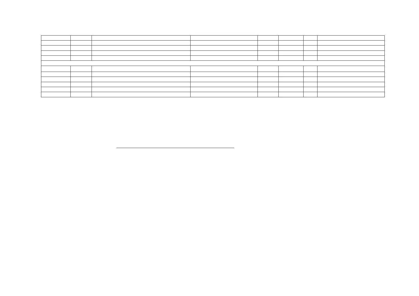
Address Point ID Description Options/Range Units Type R/W Notes
35680-35695 Waveform log #2, channel V3/V31 R
2
35696-35711 Waveform log #2, channel I1 R
35712-35727 Waveform log #2, channel I2 R
35728-35743 Waveform log #2, channel I3 R
Waveform Series Transfer Block
EH
6144-6655
Waveform Sample Series
3
+0 Sample point 1 -32768 to 32767 INT16 R
+1 Sample point 2 -32768 to 32767 INT16 R
+2 Sample point 2 -32768 to 32767 INT16 R
+511 Sample point 512 -32768 to 32767 INT16 R
NOTES:
1
If a file is read through a TCP connection, your assignments for the transfer will be effective only within the current connection socket. Since the device cannot guarantee that your next
connection will be made through the same socket, you should not make any assumptions regarding the present block settings. When you open a new connection, always check the file status
and pointers before reading file records.
2
When the 4LN3, 4LL3, 3LN3, 3LL3, 3BLN3 or 3BLL3 wiring mode is selected, the voltages will be line-to-neutral; for any other wiring mode, they will be line-to-line.
3
To convert digital samples to their analog equivalents in input measurement units (volts, amps), the following scaling should be applied:
SCALE_DIGITAL
2SCALE_ANALOG)OFFSET_ZEROSAMPLE_DIGITAL(
]Amps/Volts[SAMPLE_ANALOG
××−
=

 Loading...


