87
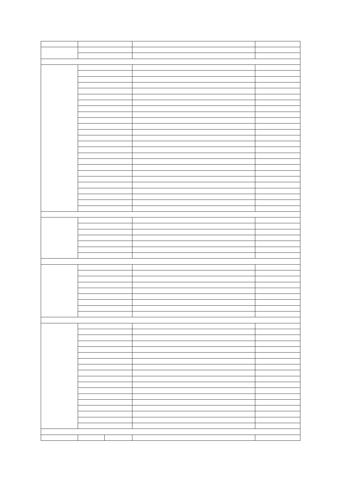
Format Code Value Description Notes
2 16-bit Analog Change Event Without Time
3 16-bit Analog Change Event With Time
DNP Class 0 Objects
0x1E01 Analog Input 30:01
0x1E02 Analog Input 30:02
0x1E03 Analog Input 30:03
0x1E04 Analog Input 30:04
0x1F01 Frozen Analog Input 31:01
0x1F02 Frozen Analog Input 31:02
0x1F03 Frozen Analog Input 31:03
0x1F04 Frozen Analog Input 31:04
0x1F05 Frozen Analog Input 31:05
0x1F06 Frozen Analog Input 31:06
0x2801 Analog Output 40:01
0x2802 Analog Output 40:02
0x0101 Binary Input 01:01
0x0102 Binary Input 01:02
0x1401 Binary Counter 20:01
0x1402 Binary Counter 20:02
0x1405 Binary Counter 20:05
0x1406 Binary Counter 20:06
0x1501 Frozen Counter 21:01
0x1502 Frozen Counter 21:02
0x1505 Frozen Counter 21:05
0x1506 Frozen Counter 21:06
0x1509 Frozen Counter 21:09
0x150A Frozen Counter 21:10
F25
0x3201 Time and Date 50:01
Log Notification Status
Bit 0 Reserved
Bit 1=1 New Min/Max Log
Bit 2=1 New Event log record
Bit 3=1 New Data log record
Bit 4=1 New Waveform log #1 record
Bit 5=1 New Waveform log #2 record
F26
Bits 6-15 Reserved
Data Log Notification Status
Bit 0=1 New Data log #1 record
Bit 1=1 New Data log #2 record
Bit 2=1 New Data log #3 record
Bit 3=1 New Data log #4 record
Bit 4=1 New Data log #5 record
Bit 5=1 New Data log #6 record
Bit 6=1 New Data log #7 record
Bit 7=1 New Data log #8 record
F27
Bits 8-15 Reserved
Instrument Options
Bit 0=1 120V Option
Bit 1=1 690V Option
Bits 2-5 Reserved
Bit 6=1 Analog output 0/4 or 4/20mA
Bit 7=1 Analog output 0-1mA
Bit 8=1 Analog output ±1mA
Bit 9=1 RO option
Bit 10=1 DI option
Bit 11=1 Reserved
Bit 12=1 Setup is secured by a password (authorization required)
Bit 13=1 Reserved
Bit 14=1 Analog expander option ±1mA
Bit 15 Reserved
Bits 16-18 Number of RO - 1
Bits 19-22 Number of DI – 1
Bits 23-24 Number of AO - 1
Bits 25-29 Reserved
F28
Bits 30-31=11
Memory module 1MBytes
E
I/O Slot Types
F29 DI DRY 00000000B
× = Don’t care

 Loading...


