3.51
Date Code 20170601 Instruction Manual SEL-387-0, -5, -6 Relay
Differential, Restricted Earth Fault, Thermal, and Overcurrent Elements
Overcurrent Element
51Pn–Phase Inverse-Time Element
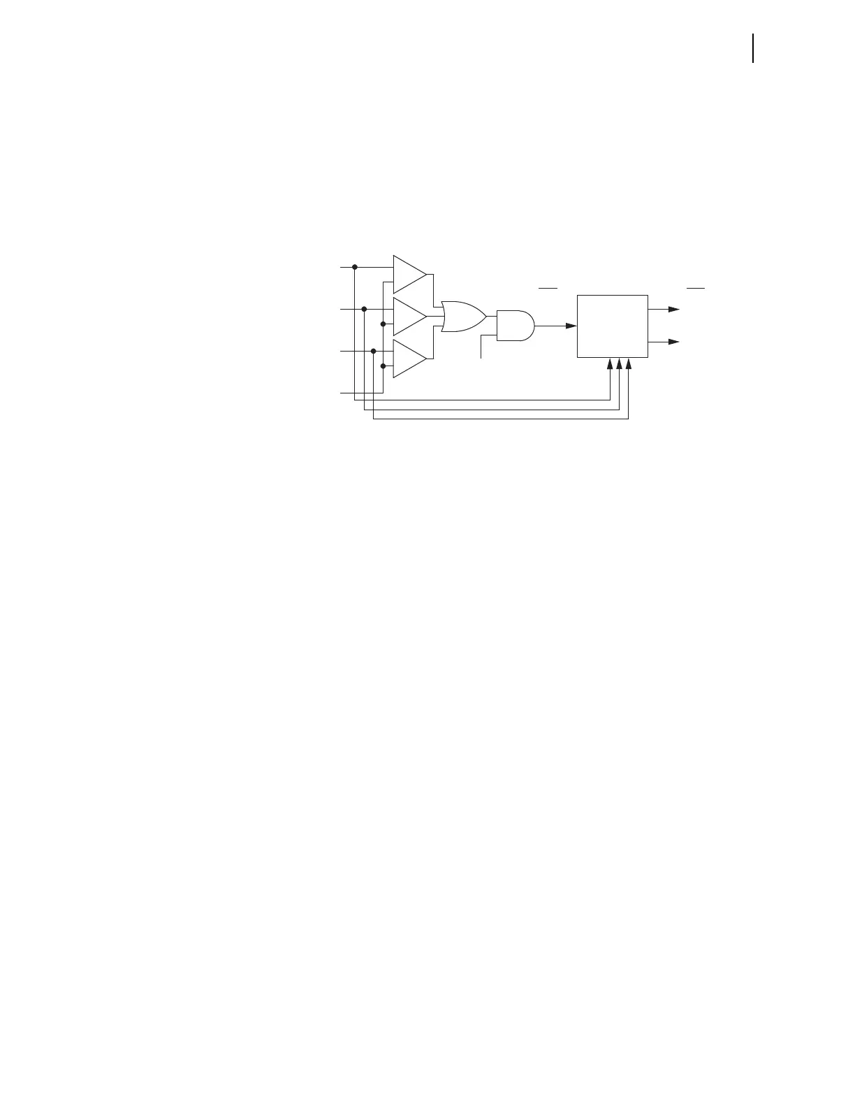
Figure 3.21 shows the logic for the 51Pn element. The logic compares the
magnitudes of phase input currents IAWn, IBWn, and ICWn to pickup setting
51PnP. If one or more current magnitudes exceed the pickup level, a logical 1
asserts at one input to the AND gate at the center. The torque-control
SEL
OGIC control equation 51PnTC determines the other AND input. If
51PnTC is true, Relay Word bit 51Pn asserts and the inverse curve begins
timing.
Figure 3.21 51Pn Phase Inverse-Time O/C Element, Torque Controlled
Four settings define an inverse-time curve: the pickup setting, 51PnP, acts as a
horizontal scaling factor, because the curve formula uses current multiple of
pickup as an input; the curve setting, 51PnC, defines the particular curve
equation, of which there are 10 (five U.S. and five IEC); the time-dial setting,
51PnTD, defines the time dial, which scales the curve in a vertical direction to
vary the output timing for a given multiple of pickup; and the reset setting,
51PnRS, defines whether the curve resets slowly like an electromechanical
disk or instantaneously when current drops below pickup. The phase inverse-
time curve looks at all three phase current magnitudes and times on the basis
of the greatest current of the three. It updates this maximum phase current
selection every quarter-cycle.
If the curve times out, Relay Word bit 51PnT asserts. When all phase currents
drop below pickup, with or without a curve time-out, 51Pn deasserts and the
element resets according to setting 51PnRS. At the completion of the reset,
Relay Word bit 51PnR asserts. This bit normally will be at logic state 1, when
the element is at rest during normal system operation. Use the TAR command
via a serial port or the front panel to verify the state of this bit. You can use the
Level 2 serial port command RES or the front-panel RESET51 function under
the {OTHER} pushbutton to force this bit to logical 1 during element testing.
This saves time if you have chosen electromechanical reset.
50Qn1 and 50Nn1–Sequence Current Definite-Time Element Logic
Figure 3.22 shows the logic for the definite-time 50Qn1 negative-sequence
element and the definite-time 50Nn1 residual element.
+
–
51PnT
(curve timeout)
–
+
+
–
51Pn
(n = Winding 1, 2, 3, or 4)
|IAWn|
|IBWn|
|ICWn|
51PnP
51PnP (pickup)
51PnC (curve)
51PnTD (time dial)
51PnRS (E/M reset)
(1 cycle if RS = N,
curve if RS = Y)
Phase
Currents
Timing
51PnR (reset)
51PnTC (SEL
OGIC
control equation TRUE)
Relay
Word
Bits
Relay
Word
Bit