3.54
SEL-387-0, -5, -6 Relay Instruction Manual Date Code 20170601
Differential, Restricted Earth Fault, Thermal, and Overcurrent Elements
Overcurrent Element
torque-control SELOGIC control equation, 51NnTC, determines the other
AND input. If 51NnTC is true, Relay Word bit 51Nn asserts and the inverse
curve begins timing.
The settings defining the curve in this case are 51NnP for the pickup setting,
51NnC for the particular curve equation, 51NnTD for the time dial, and
51NnRS for the curve reset.
Curve time-out causes Relay Word bit 51NnT to assert. When the current
drops below pickup, 51Nn deasserts and the element resets according to the
setting for 51NnRS. At the completion of the reset, Relay Word bit 51NnR
asserts. This bit normally is at logic state 1, when the element is at rest during
normal system operation. You can use the TAR command to verify the state of
the bit. You can use the Level 2 serial port command RES or the front-panel
RESET51 function under the {OTHER} pushbutton to force the bit to a logical 1
during element testing.
51PCm and 51NCm Combined Overcurrent Element (m = 1, 2)
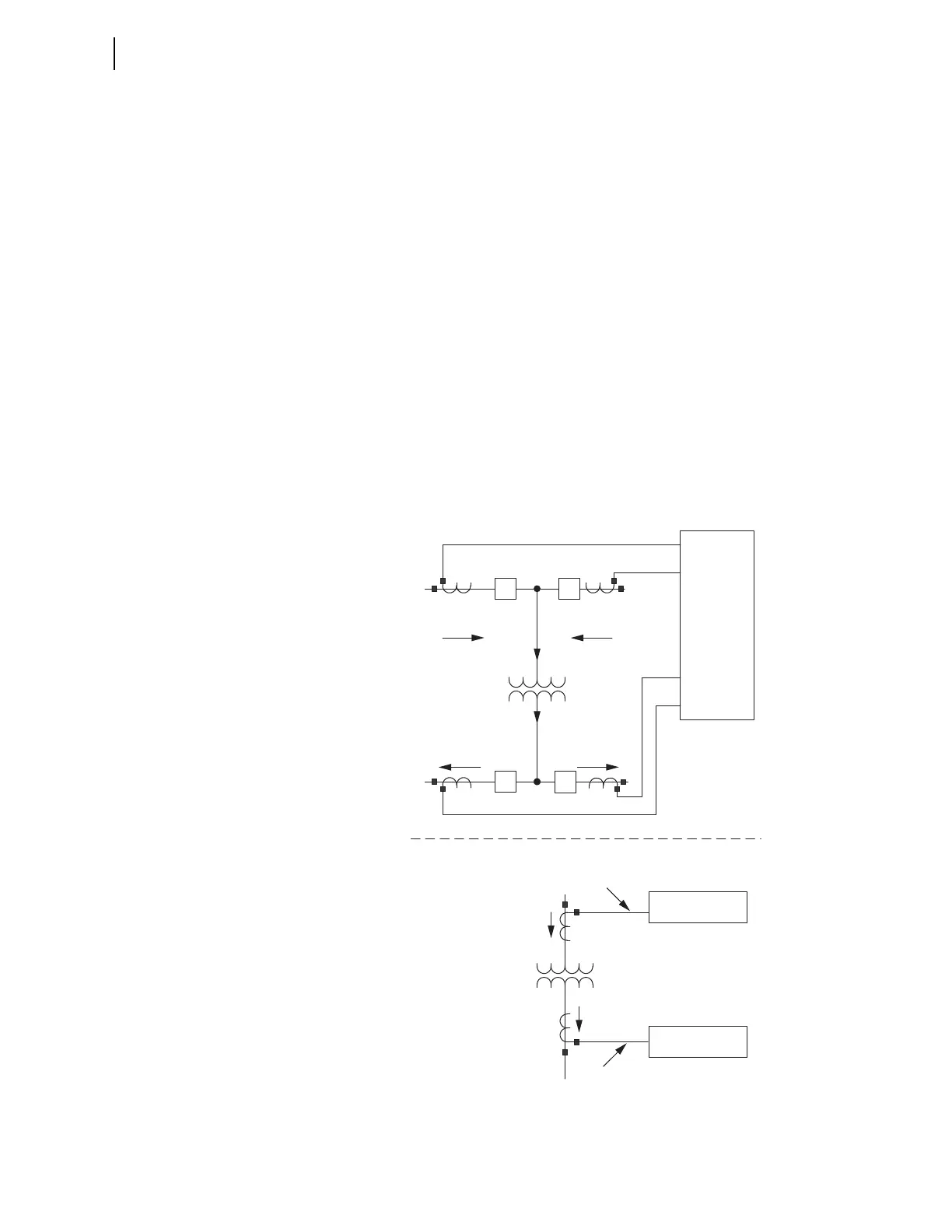
The combined overcurrent elements operate on summed input currents to two
windings. Elements 51PC1 and 51NC1 use phase and residual current from
Windings 1 and 2, while 51PC2 and 51NC2 use these currents from
Windings 3 and 4; see Figure 3.25.
Figure 3.25 Combined Overcurrent Example
1200 A
3800 A
CT4 CT3
SEL-387
CB4 CB3
W1
2500 A1300 A
CT Equivalent 1 and 2
CT Equivalent 3 and 4
W3 and W4
Combination:Windings 3 and 4
W1 and W2
Combination:Windings 1 and 2
3800 A
1200 A
500 A
700 A
CT1 CT2CB1 CB2
W2
W3
W4


 To Next Page