2.10
SEL-387-0, -5, -6 Relay Instruction Manual Date Code 20170601
Installation
Rear-Panel Connections
Current Transformer Inputs
Connect current inputs to the four sets of current input terminals. Note that the
CT shorting connectors providing current connections to Connectorized relays
install in only one orientation. Note also that the current input terminals on
both terminal block and Connectorized relays have a mark at one terminal per
phase to indicate polarity. Each current input is independent of the other two
inputs. Current inputs are designated IAW1, IBW1, ICW1; IAW2, IBW2, ICW2; IAW3,
IBW3, ICW3; and IAW4, IBW4, and ICW4.
Optoisolated Inputs
Connect control input wiring to the six standard inputs IN101–IN106 and to any
of the interface board optoisolated inputs IN201–IN208 you need for your
application.
All control inputs are dry optoisolated inputs and are not polarity dependent.
Specify a nominal rated control voltage of 48, 110, 125, 220, or 250 Vdc for
level sensitive and 24 Vdc for nonlevel sensitive when ordering. To assert an
input, apply nominal rated control voltage to the terminals assigned to that
input. A terminal pair is brought out for each input. Refer to General on
page 1.8 for optoisolated input ratings. There are no internal connections
between inputs. ON and OFF values are normally within one volt of each
other, in the indicated range.
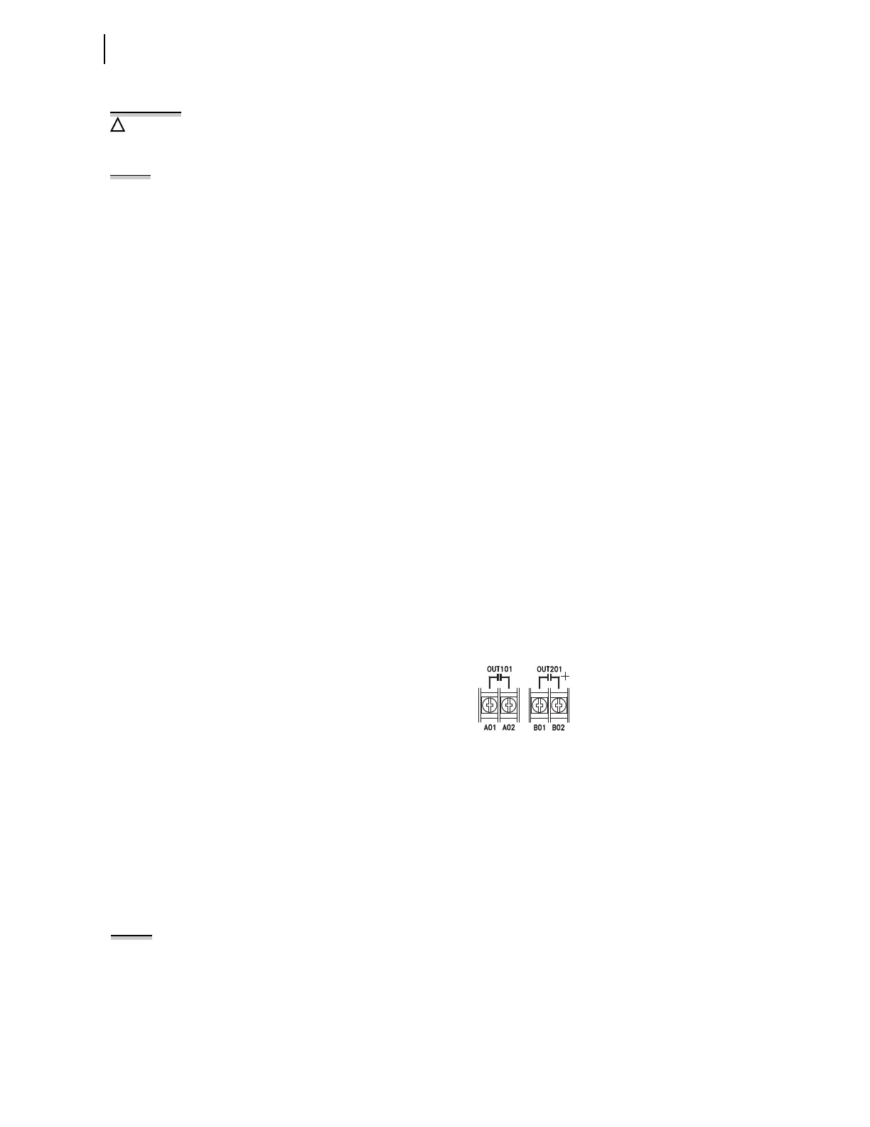
Output Contacts
Connect output wiring to the SEL-387 main board eight standard independent
output contacts, OUT101 through OUT107 and ALARM. Standard independent dry
output contacts are not polarity dependent; the left side of Figure 2.7 shows
these contacts as they would appear on a terminal block version.
Figure 2.7 Standard Independent Output Contact Representation
Connect output wiring to any of the additional output contacts OUT201–OUT212
you need for your application. On the additional interface board, you have the
option of either standard or high current interrupting contacts. High current
interrupting contacts are polarity dependent. A plus polarity mark next to
the terminal requiring positive dc voltage identifies these contacts on a relay
rear panel. The right side of Figure 2.7 shows this polarity mark for high
current interrupting contacts. Ensure correct polarity; reversed polarity causes
a short circuit to appear across the contact terminals.
Communications Port
Refer to Table 2.1 for a list of cables that you can purchase from SEL for
various communication applications. Refer to Section 7: Serial Port
Communications and Commands for detailed cable diagrams for selected
cables.
Before working on a CT circuit, first
apply a short to the secondary
winding of the CT.
NOTE: When installing CT shorting
connectors, ensure that you secure
each connector to the relay chassis
with the screws at each connector
end. When removing a CT shorting
connector, pull it straight away from
the relay rear panel. Removing a
shorting connector causes internal
mechanisms within the
connector to
individually short out each power
system current transformer.
NOTE: Listing of devices not
manufactured by SEL is for the
convenience of our customers. SEL
does not specifically endorse or
recommend such products nor does
SEL guarantee proper operation of
those products, or the correctness of
connections, over which SEL has no
control.