H.20
SEL-387-0, -5, -6 Relay Instruction Manual Date Code 20170601
Protection Application Examples
Transformer Winding and CT Connection Compensation Settings Examples
Quick Settings Guide
for Standard
Connections
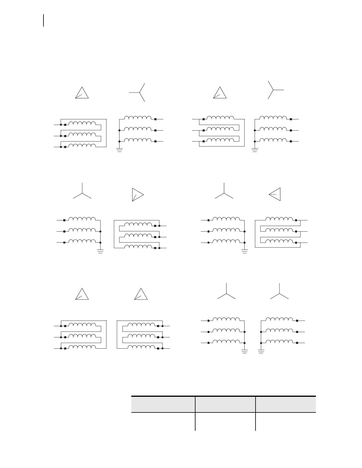
Figure H.29 shows examples of common transformer connections. Table H.4
is a quick reference guide to be used when all standard phase-to-bushing, CT,
and relay connections are present. Table H.4 is applicable to both ABC and
ACB system phase rotations.
Figure H.29 Common Transformer Connections
H2
H3
H1
Winding 1
H3
H2
H1
X3
X2
X1
X3
X2
X1
X0
Winding 1
H3
H2
H1
X1
X2
X3
X3
X2
X1
X0
H2
H3
H1
Winding 2 Winding 2
DABY/Dy1 DACY/Dy11
Winding 2
X3
X2
X1
X2
X3
X1
H3
H2
H1
Winding 1
H3
H2
H1
H0
H3
H2
H1
Winding 1
H3
H2
H1
H0
X2
X3
X1
Winding 2
X3
X2
X1
YDAB/Yd11 YDAC/Yd1
H2
H3
H1
Winding 1
H3
H2
H1
Winding 2
X3
X2
X1
X2
X3
X1
H3
H2
H1
Winding 1
H3
H2
H1
H0
X3
X2
X1
Winding 2
X3
X2
X1
H0
DABDAB/Dd0 YY/Yy0
Table H.4 Quick Settings Guide for Common Transformer Configurations and
Standard Connections (Sheet 1 of 2)
XFMR Connection
W1CTC
(Winding 1)
W2CTC
(Winding 2)
DABY/Dy1 0 1
DACY/Dy11 0 11


 To Next Page