H.4
SEL-387-0, -5, -6 Relay Instruction Manual Date Code 20170601
Protection Application Examples
Transformer Winding and CT Connection Compensation Settings Examples
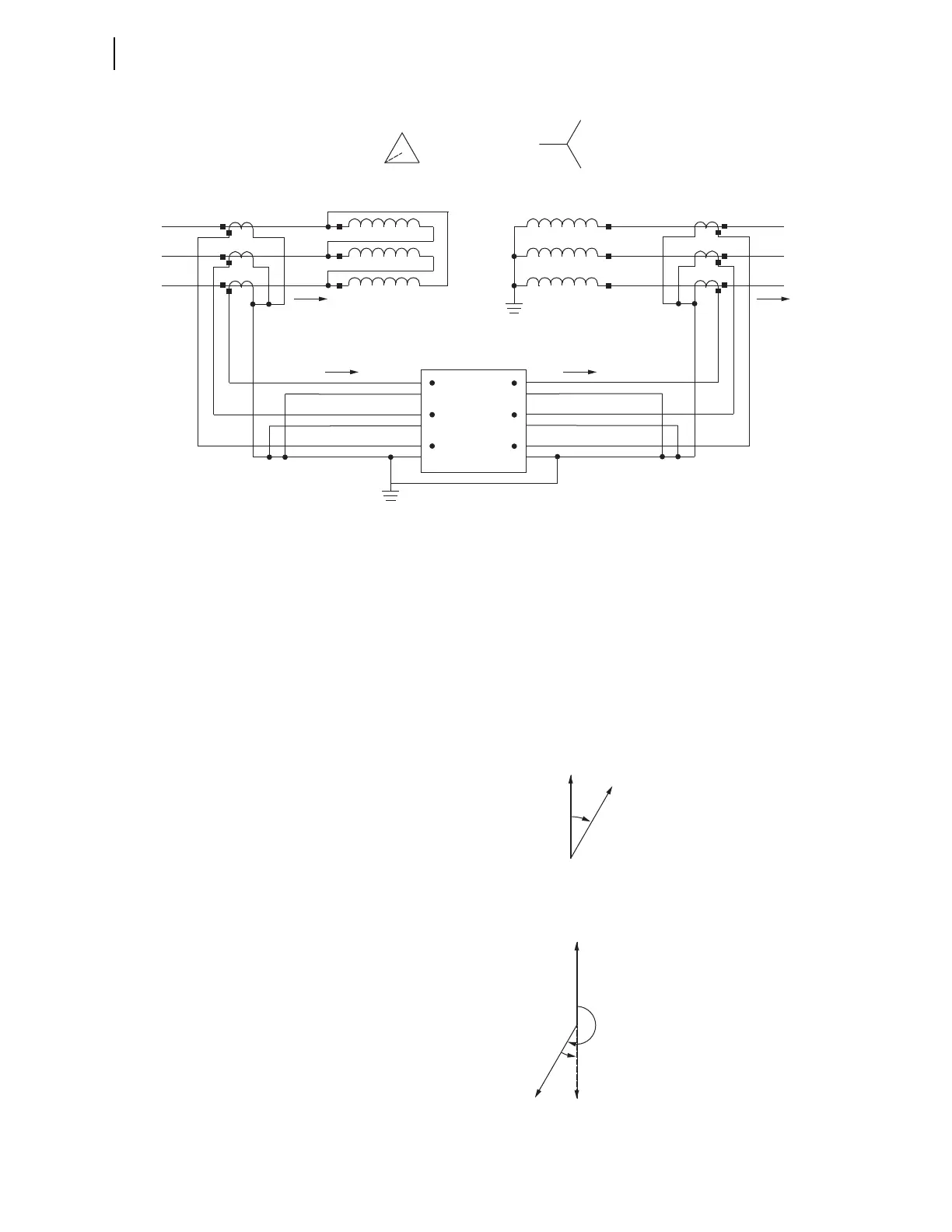
Figure H.2 Three-Line Diagram Showing System Phase-to-Transformer Bushing, CT, and CT-to-Relay
Connections
If all the connections are standard as shown in Figure H.2, under a through-
load condition the phase relationship between the system primary currents
(Ia system and IA system) and corresponding secondary currents as seen by
the relay (IAW2 and IAW1) will look like as shown in Figure H.3 (Ia lags IA
by 30 degrees) and Figure H.4 (IAW2 lags IAW1 by 210 degrees),
respectively. The goal of the compensation settings is to compensate IAW2 so
as to bring IAW2_compensated 180 degrees out-of-phase with IAW1 for
proper application of the differential function.
Figure H.3 Primary Current Phasors
Figure H.4 Current at the Relay Terminals
B (H2)
C (H3)
A (H1)
Winding 1 Winding 2
A
B
C
a
b
c
SEL-387
(Partial)
IAW1
IBW1
ICW1
IAW2
IBW2
ICW2
H3
H2
H1
X3
X2
X1
IA System Ia System
IA Relay Ia Relay
c (X3)
b (X2)
a (X1)
IAW1
IAW2
Secondary
210°
IAW2_Compensated
30°