3.53
Date Code 20170601 Instruction Manual SEL-387-0, -5, -6 Relay
Differential, Restricted Earth Fault, Thermal, and Overcurrent Elements
Overcurrent Element
input to the AND gate. The torque-control SELOGIC control equation,
50Qn2TC, determines the other AND input. If 50Qn2TC is true, Relay Word
bit 50Qn2 asserts.
50Nn2 Residual Instantaneous Element
The 50Nn2 element compares the magnitude of the calculated residual
current, IRWn, to the pickup setting, 50Nn2P. If the calculated residual current
exceeds the pickup level, a logical 1 asserts at one input to the AND gate. The
torque-control SEL
OGIC control equation, 50Nn2TC, determines the other
AND input. If 50Nn2TC is true, Relay Word bit 50Nn2 asserts.
51Qn and 51Nn–Sequence Inverse-Time Elements
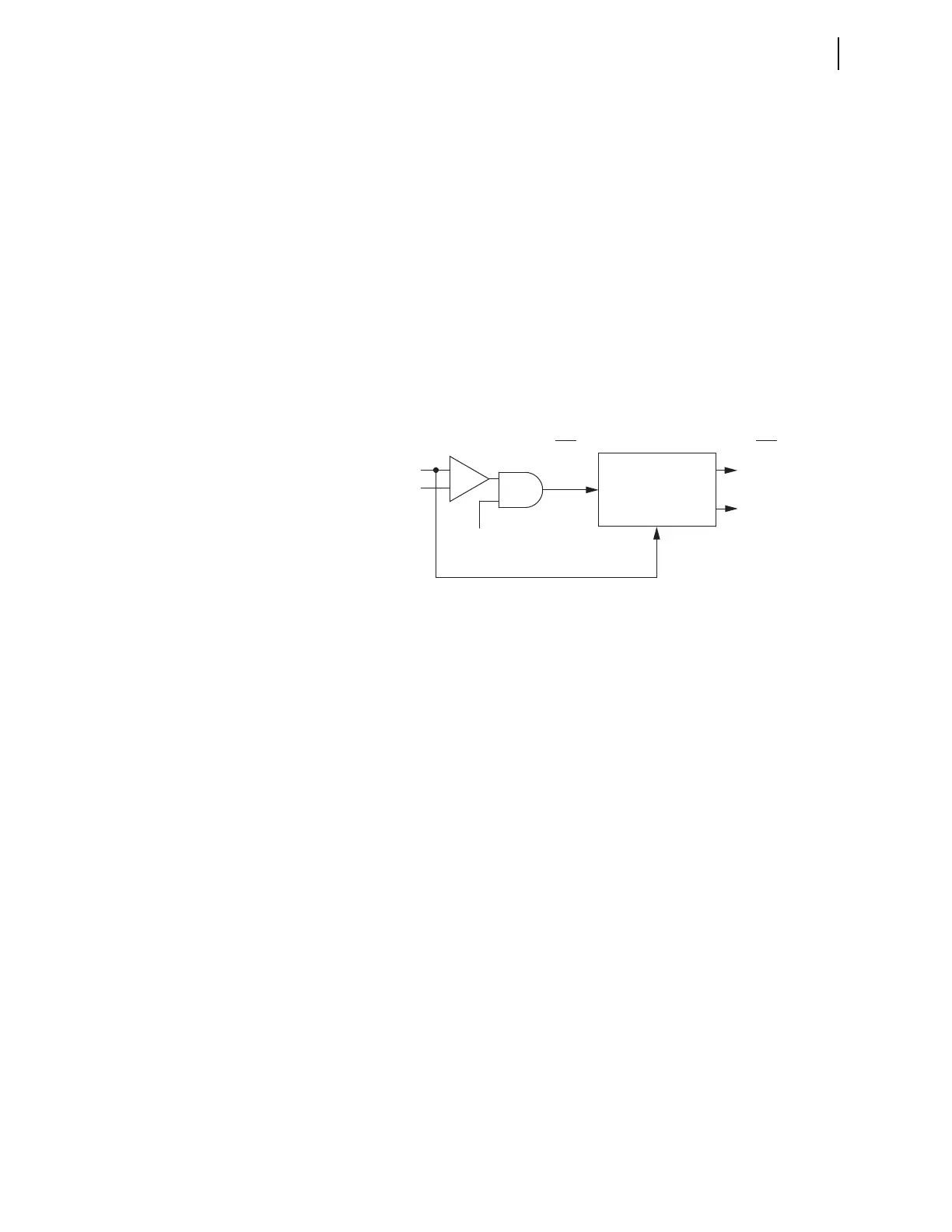
Figure 3.24 shows the logic for the inverse-time 51Qn negative-sequence
element and the inverse-time 51Nn residual element.
Figure 3.24 51Qn and 51Nn Sequence Inverse-Time O/C Element,
Torque Controlled
51Qn Negative-Sequence Inverse-Time Element
The 51Qn element logic compares the magnitude of the calculated negative-
sequence current, 3I2Wn, to the pickup setting, 51QnP. If the calculated
negative-sequence current exceeds the pickup level, a logical 1 asserts at one
input to the AND gate at the center. The torque-control SEL
OGIC control
equation, 51QnTC, determines the other AND input. If 51QnTC is true, Relay
Word bit 51Pn asserts and the inverse curve begins timing.
As with phase inverse-time element logic, four settings define the curve. In
this case 51QnP is the pickup, 51QnC defines the curve equation, 51QnTD
defines the time dial, and 51QnRS determines how the curve resets.
Curve time-out causes Relay Word bit 51QnT to assert. When the current
drops below pickup, 51Qn deasserts and the element resets according to the
setting for 51QnRS. At the completion of the reset, Relay Word bit 51QnR
asserts. This bit normally is at logic state 1, when the element is at rest during
normal system operation. You can use the TAR command to verify the state of
the bit. You can use the Level 2 serial port command RES or the front-panel
RESET51 function under the {OTHER} pushbutton to force the bit to a logical 1
during element testing. This saves time if you have chosen electromechanical
reset.
51Nn Residual Inverse-Time Element
The 51Nn element compares the magnitude of the calculated residual current,
IRWn, to the pickup setting, 51NnP. If calculated residual current exceeds the
pickup level, a logical 1 asserts at one input to the AND gate at the center. The
Relay
Word
Bits
Relay
Word
Bits
(n = Winding 1, 2, 3, or 4)
51QnP (51NnP) (pickup)
51QnC (51NnC) (curve)
51QnTD (51NnTD) (time dial)
51QnRS (51NnRS) (E/M reset)
(1 cycle if RS = N,
curve if RS = Y)
Sequence
Current
Timing
+
–
(51Nn)
51Qn
51QnT (51NnT)
(curve timeout)
51QnR (51NnR)
(reset)
51QnTC (51NnTC)
(SEL
OGIC control
equation TRUE)
|3I2Wn| (|IRWn|)
51QnP (51NnP)