H.2
SEL-387-0, -5, -6 Relay Instruction Manual Date Code 20170601
Protection Application Examples
Transformer Winding and CT Connection Compensation Settings Examples
As shown in Section 3: Differential, Restricted Earth Fault, Thermal, and
Overcurrent Elements (Table 3.1), compensation matrix CTC(0) multiplies the
currents by the identity matrix and creates no change in the currents.
Compensation matrix CTC(12) is similar to CTC(0) in that it produces no
phase shift (or, more correctly, 360 degrees of shift) in a balanced set of
phasors separated by 120 degrees. However, CTC(12) removes zero-sequence
components from the measured current, as do all of the matrices with
non-zero values.
Transformer
Nameplates and
System Connections
To determine the phase shift seen by the relay, the following information is
required:
➤ Transformer phasor (vector) diagram (transformer nameplate)
➤ Three-line connection diagram showing:
➢ System phase-to-transformer bushing connections
➢ CT connections
➢ CT-to-relay connections
Figure H.1 shows the key information from a typical nameplate for a two-
winding transformer. The winding connection diagram and the phasor (vector)
diagram are needed to determine the winding compensation settings in the
relay.
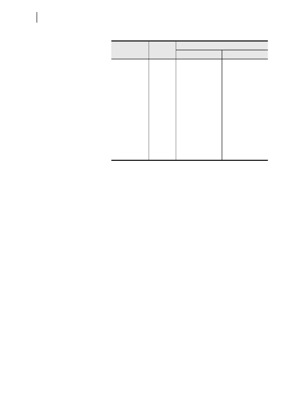
Table H.1 WnCTC Setting: Corresponding Phase and Direction of Correction
WnCTC Setting
a
a
n=1, 2, 3, 4.
Matrix
Amount and Direction of Correction
ABC Phase Rotation ACB Phase Rotation
0CTC(0)0° 0°
1 CTC(1) 30° CCW 30° CW
2 CTC(2) 60° CCW 60° CW
3CTC(3)
90° CCW 90° CW
4 CTC(4) 120° CCW 120° CW
5 CTC(5) 150° CCW 150° CW
6 CTC(6) 180° CCW 180° CW
7 CTC(7) 210° CCW 210° CW
8 CTC(8) 240° CCW 240° CW
9 CTC(9) 270° CCW 270° CW
10 CTC(10) 300° CCW 300° CW
11 CTC(11) 330° CCW 330° CW
12 CTC(12)
0° (360°) CCW 0° (360°) CW