H.17
Date Code 20170601 Instruction Manual SEL-387-0, -5, -6 Relay
Protection Application Examples
Transformer Winding and CT Connection Compensation Settings Examples
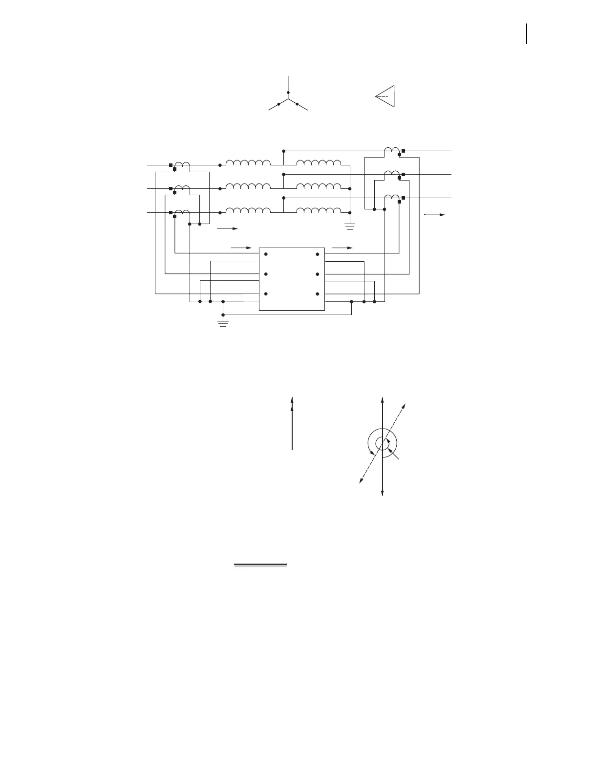
Figure H.23 Autotransformer With Standard Phase-to-Bushing Connections
Figure H.24 Primary Currents and Secondary Currents as Measured by the
Relay
Special Cases
EXAMPLE H.5 Delta-Wye Transformer With Standard
Phase-to-Bushing Connections, Standard CT Connections, and an
ACB System Phase Rotation
Consider the application in Figure H.25 with standard
phase-to-bushing connections, standard CT connections, and an ACB
system phase rotation.
X1
X2
X3
H3
H2
H1
C
B
A
c
b
a
B (H2)
C (H3)
A (H1)
a (T1)
b (T2)
c (T3)
a (X1)
b (X2)
c (X3)
IAW1
IBW1
ICW1
IAW2
IBW2
ICW2
SEL-387
(Partial)
IA System
Ia System
Winding 1 Winding 2
IA Relay Ia Relay
Ia
Primary
IA
Secondary
IAW1
IAW2
IAW1 (Compensated)
IAW2
(Compensated)
330°
330°


 To Next Page