H.10
SEL-387-0, -5, -6 Relay Instruction Manual Date Code 20170601
Protection Application Examples
Transformer Winding and CT Connection Compensation Settings Examples
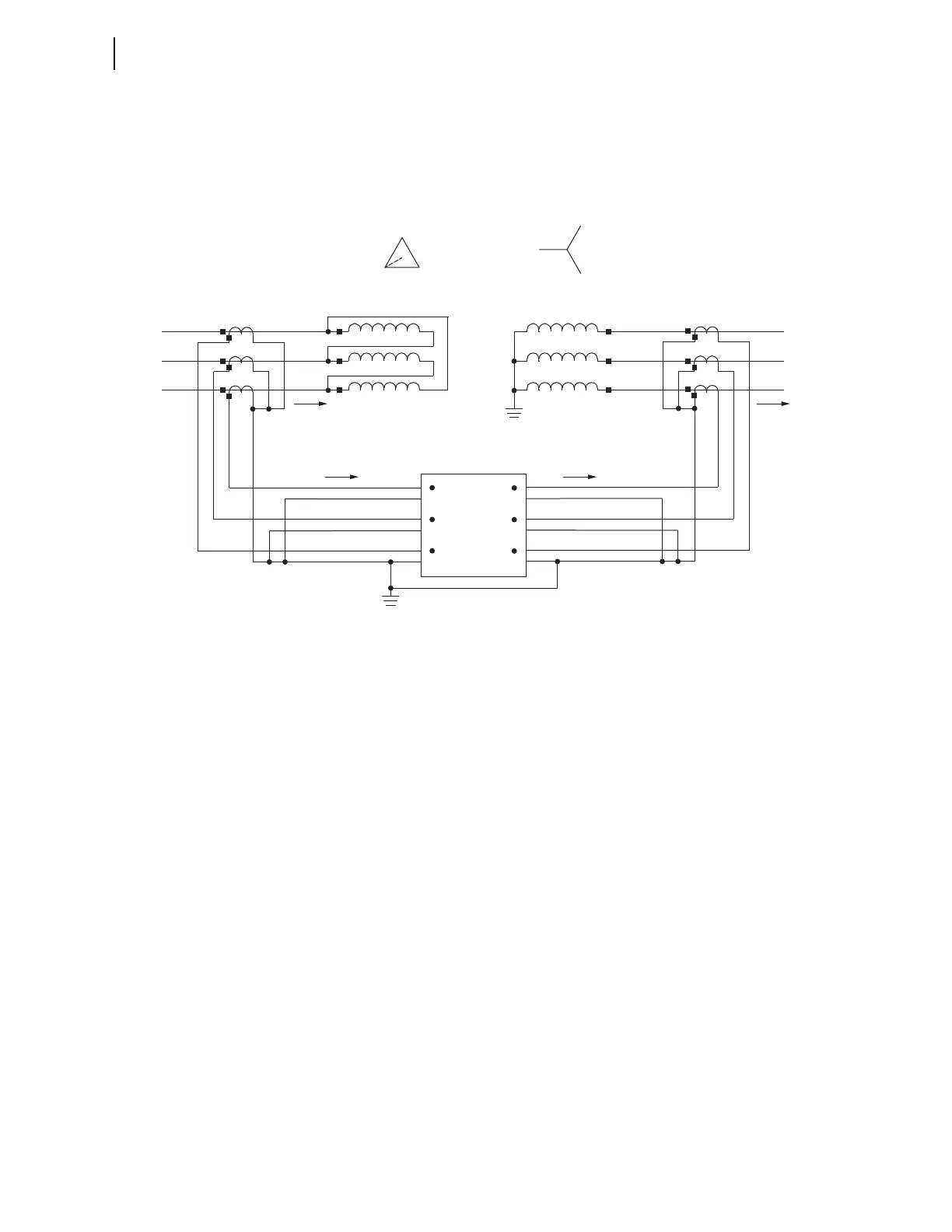
Non-Standard CT Connections: Reversed CT Polarity. Figure H.13
shows the X-side CT polarity marks toward the transformer. However,
because the connections to the relay remain the same, the relay currents flow
the same, as in Figure H.12. No additional adjustments need to be made
because of this type of non-standard CT connection.
Figure H.13 Current Flow With Reversed X-Side CT Polarity
Non-Standard CT Connections: Reversed CT Polarity and Reversed
Connections. In Figure H.14, the polarity marks of the X-side CTs are
toward the transformer, as in Figure H.13, but the neutral sides of the CTs are
away from the transformer. With these connections, the H-side and X-side
currents are both entering the relay at the relay polarity mark.
B (H2)
C (H3)
A (H1)
Winding 1 Winding 2
A
B
C
a
b
c
SEL-387
(Partial)
IAW1
IBW1
ICW1
IAW2
IBW2
ICW2
H3
H2
H1
X3
X2
X1
IA System Ia System
IA Relay Ia Relay
c (X3)
b (X2)
a (X1)