3 Operation
3--25
F--9999--8 Build 8 Issue 1
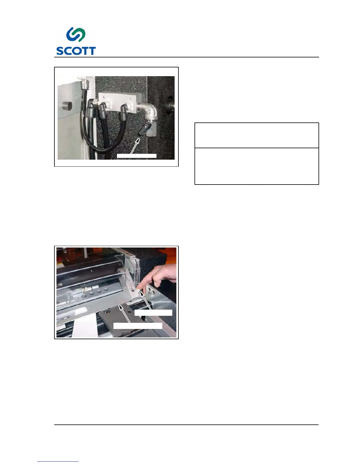
EXHAUST VALVE
Fig. 3-48. Adjust the Air Blow At the Exhaust
Valve
The amount of blow--air from the nozzles can be
adjusted by use of the exhaust valve located on
the feeder guards.
The right exhaust valve controls the RH side air
blow nozzle and RH top air blow nozzle. The left
exhaust valve controls the LH side and top air
nozzles.
DO NOT RESTRICT THE BLOW AIR TO
THE POINT WHERE IT OVERLOADS
THE VACUUM PUMP. THIS CAN CAUSE
THE MOTOR TO BE DAMAGED.
CAUTION!
Step: 1. Use exhaust valve to adjust over all blow air for all four blow air nozzles.
● The higher the vacuum, the more closed this valve will need to be.
● Heavier stocks will need more blow air, lighter stock will need less blow air.
● The higher the vacuum is set, the less blow air is available.
Step: 2. Open valves until the stock touches the separator fingers. Adjust the air valves according to size
and weight of the stock.
THUMB SCREW
WINDOW ASSEMBLY
Fig. 3-49. Plastic Feed Window Adjustment
3.3.1.4 Plastic Feed Window Adjustment
The plastic feed window holds the Mylar in its
proper open position.
To adjust the window:
Step: 1. Loosen the jam nut on the plastic thumb
screw.
Step: 2. Rotate the thumb screw
counter--clockwise until the window
assembly is touching the tip die and the
plastic feed tunnel.
Step: 3. Lift up the window assembly and place a
piece of index stock (from current
production run) and place it over the tip
die area.
Step: 4. Set the window assembly down on top of
the index stock and slowly turn the thumb
screw clockwise until the index stock can
be slide back and forth easily without any
resistance.
Step: 5. Gently retighten the jam nut.