D.2
SEL-734B Capacitor Bank Control Field Reference Guide Date Code 20170207
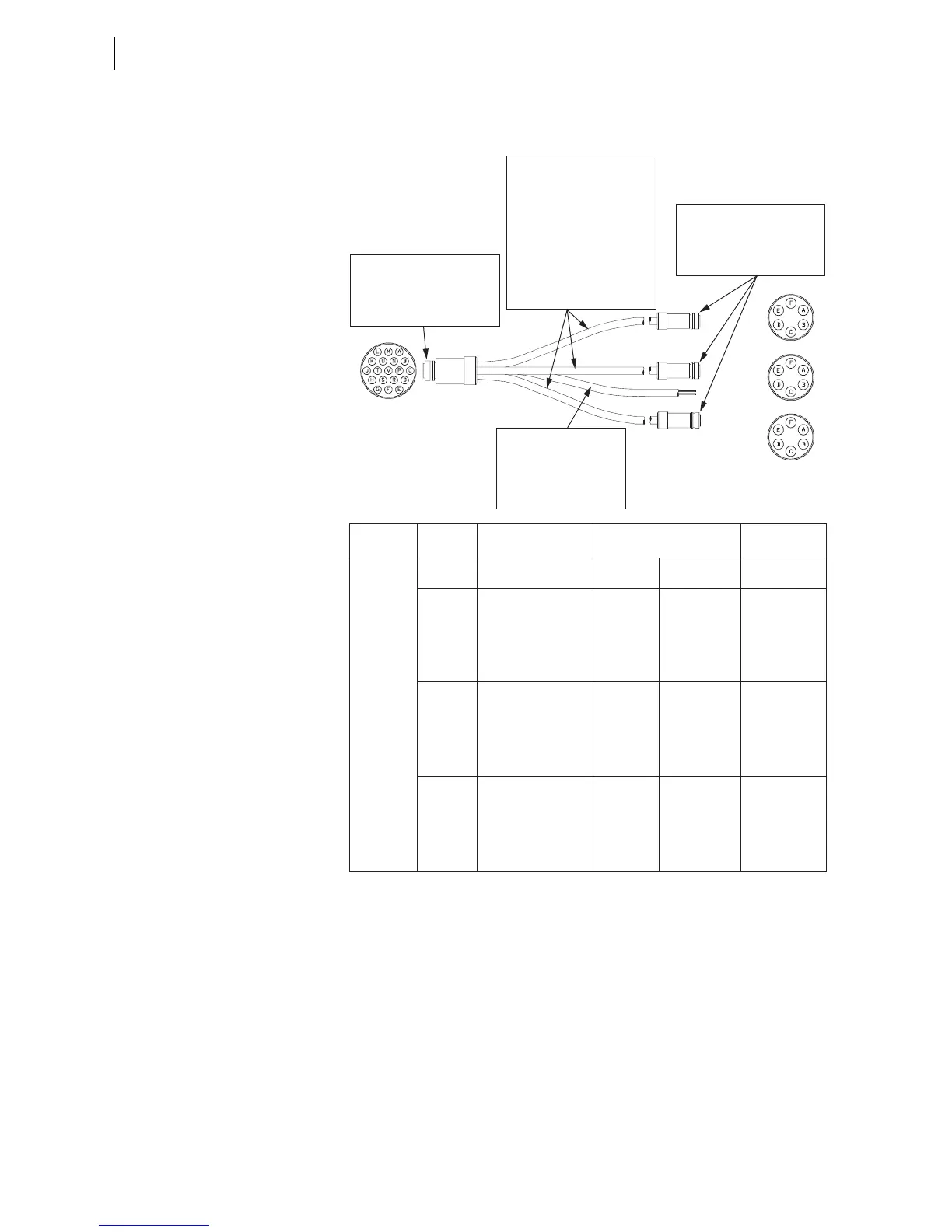
Cable Drawings
Control Cables for Full-Size Enclosures With the Combined Sensor Connector
SEL-C544
Cable SEL-C544 connects to three switches and the control power
transformer (6-pin female connectors).
J1
Phase 1
Phase 2
Phase 3
Power Supply
J4
J3
J2
Jacket:
• SOOW Cable
• 6 Conductor, 16 AWG
• Super Vu-Tron 90°C, Black
• Temperature Range:
–40° to 90°C
Industry Approvals:
• UL Flexible Cord UL Subject 62
• CSA Flexible Cord C22.2-49
• MSHA Approved
• RoHS Compliant
• Military Standard
• 3106 Style
• Insert Arrangement 22-14S
• Solid Backshell
• Maximum Diameter: 1.340 inch
• Military Standard
• 3106 Style
• Insert Arrangement 18-12S
• Solid Backshell
• Maximum Diameter: 1.220 inch
• Shielded SOOW Cable
• UL Standard 62
• UL and CSA Listed
• Temperature Rating: 90°C
• Voltage Rating: 600 V
• 2 Conductor, 12 AWG
Wire Color
Black
White
Red
White
Green
Black
Orange
Blue
Red
White
Green
Black
Orange
Blue
Red
White
Green
Black
Orange
Blue
120 VAC
Neutral
Common
Common
Close
Open
52b
52a
Common
Common
Close
Open
52b
52a
Common
Common
Close
Open
52b
52a
Wire Type
#12 AWG 65/30 Strand
#12 AWG 65/30 Strand
#16 AWG 26/30 Strand
#16 AWG 26/30 Strand
#16 AWG 26/30 Strand
#16 AWG 26/30 Strand
#16 AWG 26/30 Strand
#16 AWG 26/30 Strand
#16 AWG 26/30 Strand
#16 AWG 26/30 Strand
#16 AWG 26/30 Strand
#16 AWG 26/30 Strand
#16 AWG 26/30 Strand
#16 AWG 26/30 Strand
#16 AWG 26/30 Strand
#16 AWG 26/30 Strand
#16 AWG 26/30 Strand
#16 AWG 26/30 Strand
#16 AWG 26/30 Strand
#16 AWG 26/30 Strand
Connector Pin
J1-A
J1-B
J1-U
J1-E
J1-D
J1-C
J1-N
J1-M
J1-U
J1-H
J1-G
J1-F
J1-R
J1-P
J1-U
J1-L
J1-K
J1-J
J1-T
J1-S
Connector Pin
Wire Termination
Wire Termination
J2-A
J2-B
J2-C
J2-D
J2-E
J2-F
J3-A
J3-B
J3-C
J3-D
J3-E
J3-F
J4-A
J4-B
J4-C
J4-D
J4-E
J4-F
Function
Power Supply
Phase 1
Phase 2
Phase 3