126
Operating Instructions – Electronic Motor DRC.-..-SNI
8
Description of power section parameters
Parameters
8.6.4 Terminal assignment
Power section parameters \ terminal assignment \ binary inputs
Binary inputs
DI01 – DI04
index 8334.0,
bits 0–4
The parameters show the status of binary inputs DI00 to DI04.
Binary inputs
DI01 – DI04
index 8335.0 –
8338.0
This parameter is used to specify the assignment of binary inputs DI01 – D04. Binary
input DI00 is always assigned with /controller inhibit.
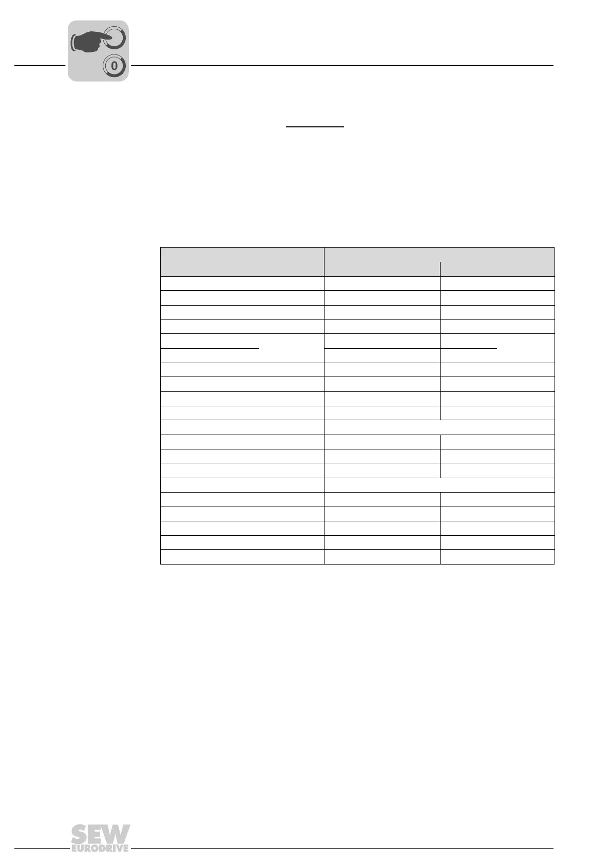
You can program the binary inputs to the following functions:
Function
Effect in case of
"0" signal "1" signal
0 = No function ––
1 = Enable/Stop Stop at t13 Enable
2 = CW/stop Stop at t11 or t12 Enable CW
3 = CCW/stop Stop at t11 or t12 Enable CCW
4 = n11
n13
External setpoints only n11
n13
5 = n12 External setpoints only n12
8 = Speed ramp 2 1st ramp (t11) active 2nd ramp (t12) active
9 = Reserved ––
10 = Reserved ––
11 = /External error, 0 active External error –
12 = Error reset Reset on positive edge ("0" to "1")
13 = Reserved ––
14 = /Limit switch right Right limit switch reached Not reached
15 = /Limit switch left Left limit switch reached Not reached
16 = IPOS input Function depends on IPOS function
17 = Reference cam Not activated Activated
18 = Reference travel start – Start referencing for IPOS
19 = Slave free running Master-slave operation Slave free running
20 = Setpoint acceptance active Do not accept Accept setpoint
30 = /Controller inhibit, 0 active Controller inhibit active Controller enabled