Operating Instructions – Electronic Motor DRC.-..-SNI
15
3
Electronics
Unit Structure
3.4 Electronics
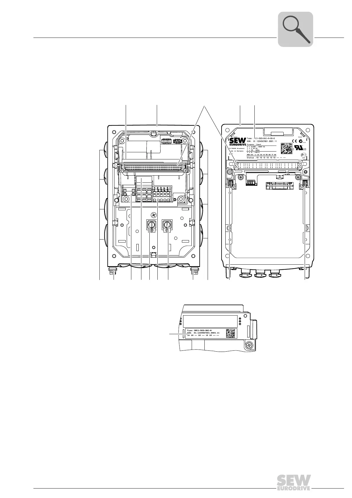
3.4.1 DRC electronics cover (inside) and connection box
The following figure shows the connection box and the bottom side of the DRC electron-
ics cover:
4762915211
[1] Nameplate of drive unit, see following detailed view
4853331979
[2] Connection box
[3] Plug connector connection unit for DRC electronics cover
[4] DRC electronics cover
[5] Electronics cover nameplate
[6] Cable glands
[7] Screws for PE connection
[8] Braking resistor connection
[9] Line connection L1, L2, L3
[10] Electronics terminal strips
[11] DIP switches S2/1 – S2/4
[12] DIP switches S1/1 – S1/4
[2][1]
[7]
[6]
[7] [7][7]
[6]
[8]
[10][9]
[11]
[12]
[3] [4] [5]