Operating Instructions – Electronic Motor DRC.-..-SNI
75
6
Description of DIP switches
Startup
6.4 Description of DIP switches
6.4.1 Overview
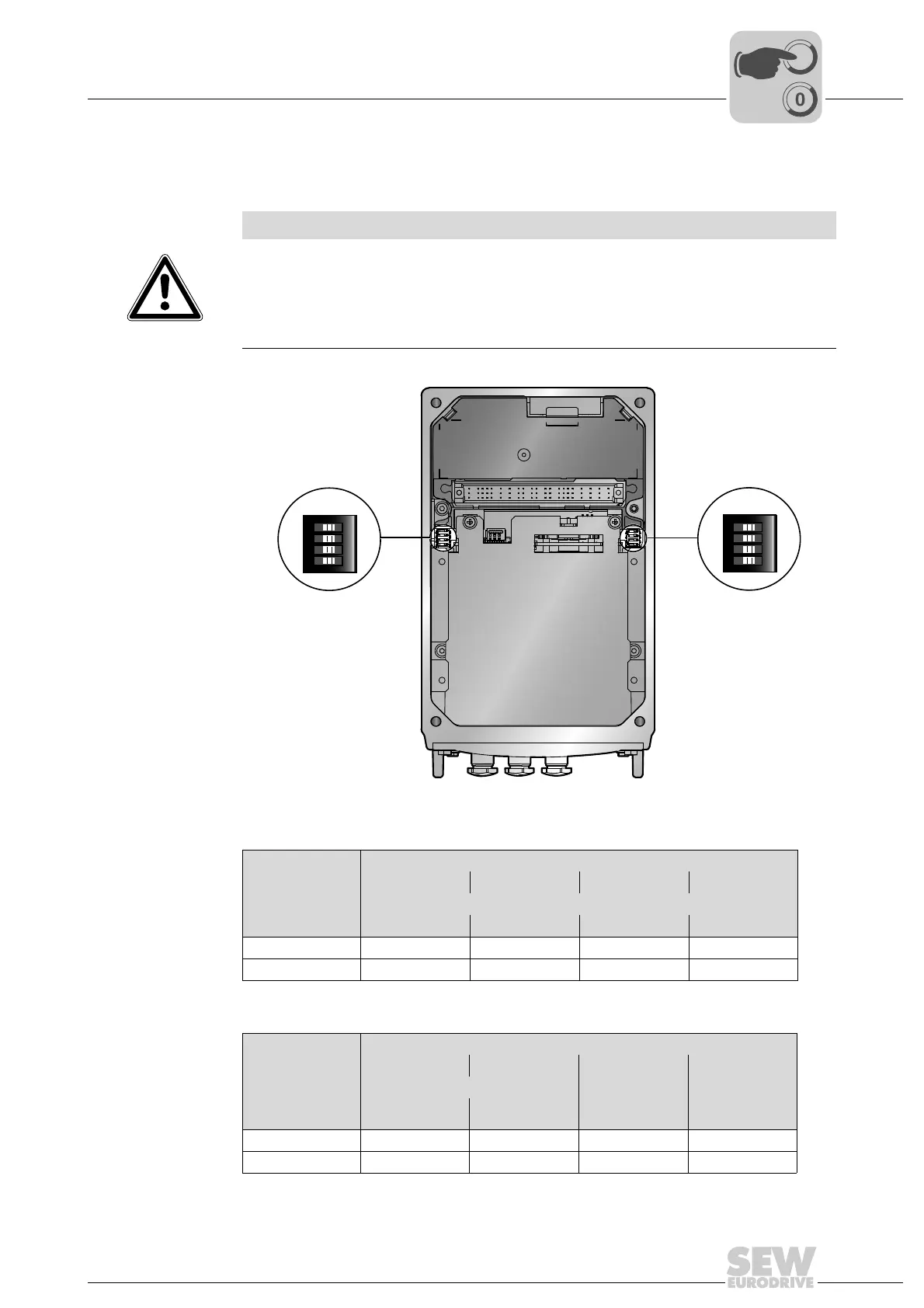
The following figure shows the DIP switches S1 and S2:
DIP switch S1 The following table shows the functions of DIP switch S1:
DIP switch S2 The following table shows the functions of DIP switch S2:
NOTICE
Damage to the DIP switches caused by unsuitable tools.
Possible damage to property.
• To set the DIP switches, use only suitable tools, such as a slotted screwdriver with
a blade width of no more than 3 mm.
• The force used for setting the DIP switches must not exceed 5 N.
9007201622737931
ON DIP
1234
S2
ON DIP
1234
S1
DIP switch S1
1 2 3 4
Binary coding SNI unit address
Bit 2
0
Bit 2
1
Bit 2
2
Bit 2
3
ON 1111
OFF 0000
DIP switch S2
1 2 3 4
Binary coding operating mode Use of the
motion control
inputs
Reserved
Bit 2
0
Bit 2
1
ON 1 1 Local mode res.
OFF 0 0 Sensors res.