76
Operating Instructions – Electronic Motor DRC.-..-SNI
6
Description of DIP switches
Startup
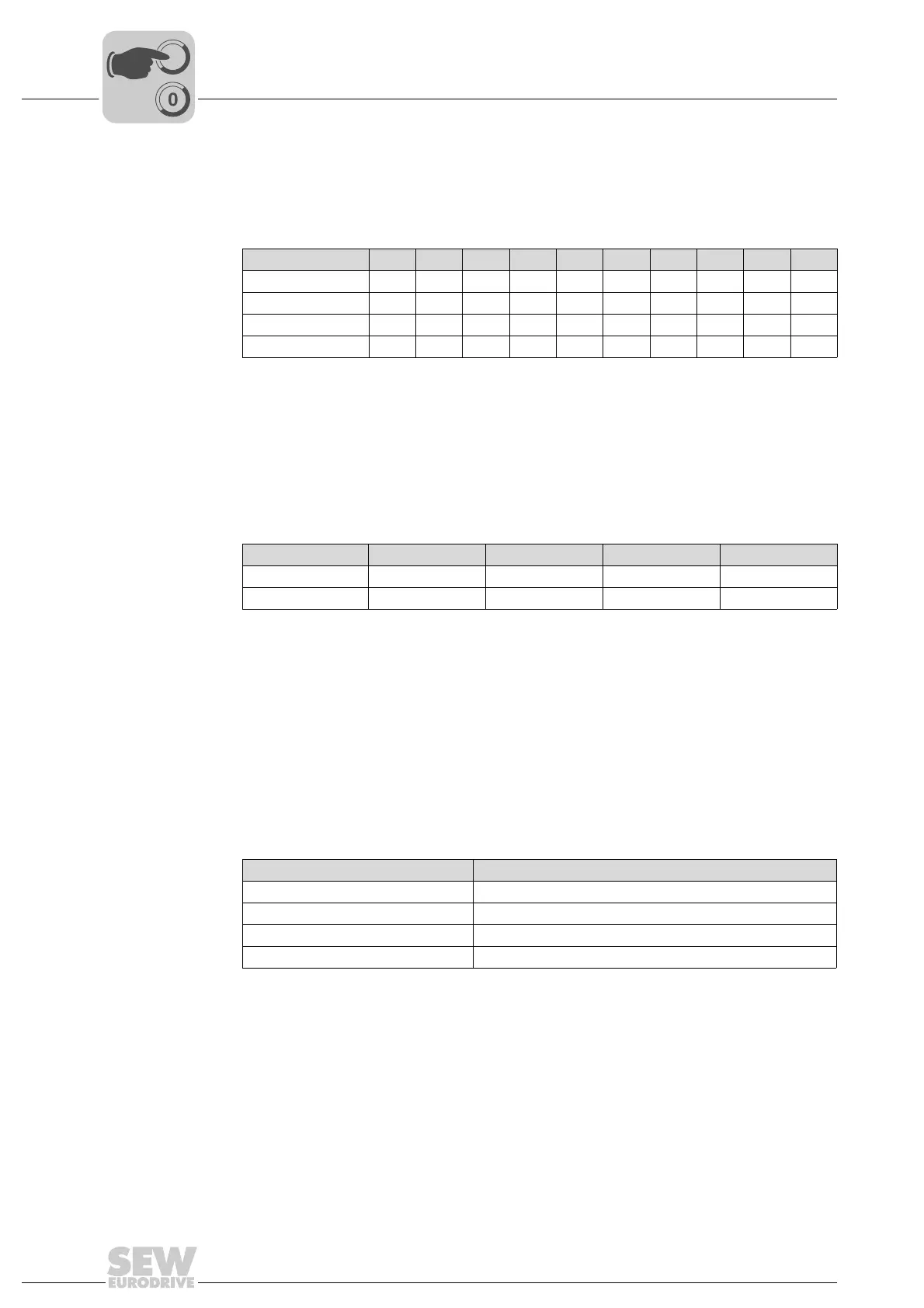
6.4.2 Description of DIP switches
DIP switches S1/1
to S1/4
Setting the SNI address
These DIP switches are used to set the SNI addresses of DRC drive units. You can set
addresses from 0 to 9. Other settings are not permitted.
DIP switches S2/1
to S2/2
Setting the operating mode
This DIP switch is used to set the operating mode of the DRC drive unit. It determines
how the unit is controlled.
When using MOVIFIT
®
SNI, the operating mode must be set to "SNI-SEWOS", when
using MOVIFIT
®
FDC SNI, it must be set to "VARIABLE".
DIP switch S2/3 Use of the motion control inputs
Use this DIP switch to determine the function of the motion control inputs (accessible
only via optional M23 plug connector).
• When DIP switch S2/3 is set to "OFF", the motion control inputs are used for
connecting and evaluating sensors. It is not possible to control the actuator via the
motion control inputs.
• When DIP switch S2/3 is set to "ON", the motion control inputs can be used for local
mode:
SNI address 0 1 2 3 4 5 6 7 8 9
S1/1 –X–X–X–X–X
S1/2 ––XX––XX––
S1/3 ––––XXXX––
S1/4 ––––––––XX
X=ON
–=OFF
Mode SNI SEWOS Reserved Reserved VARIABLE
S2/1 –X–X
S2/2 ––XX
X=ON
–=OFF
Motion control inputs Functionality with DIP switch S2/3 = ON
Motion control input 1 CW/stop
Motion control input 2 CCW/stop
Motion control input 3 Setpoint selection n_f1 / n_f2
Motion control input 4 Local/automatic