Operating Instructions – Electronic Motor DRC.-..-SNI
77
6
Startup procedure
Startup
6.5 Startup procedure
1. It is essential that you observe the startup instructions.
2. Disconnect all components from the voltage supply and use an external disconnect-
ing device to avoid unintentional re-connection.
3. Check the correct connection of all connected DRC drive units and, if installed, of the
options. Observe chapter "Electrical Installation".
4. Set the DRC unit address:
WARNING Uncontrolled drive enable due to incorrect address setting.
Severe or fatal injuries.
• Assign each device address only once.
• Check the address settings before you enable the drive for the first time.
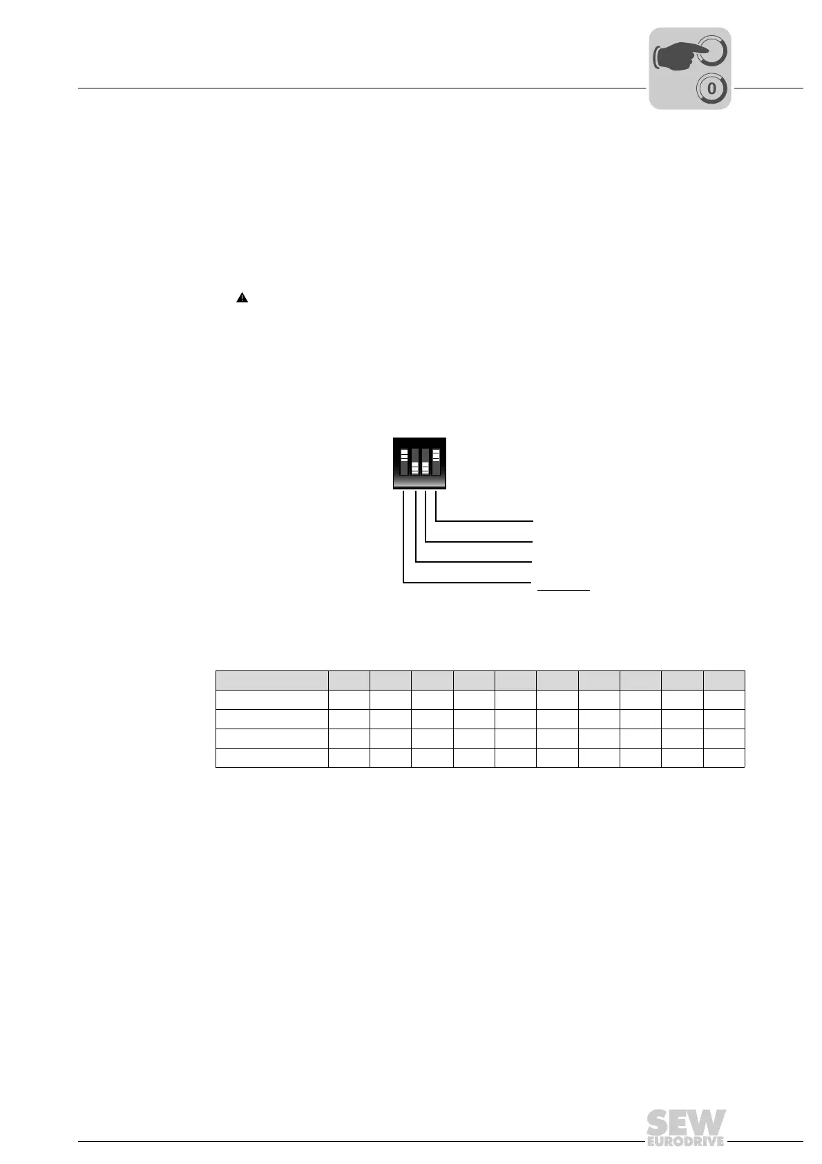
The following figure shows an example of the DIP switch setting for address 9:
The following table shows how to set the DIP switches for unit addresses 0 to 9.
Other settings are not permitted.
NOTICE Damage to the DIP switches caused by using unsuitable tools.
Possible damage to property.
• To set the DIP switches, use only suitable tools, such as a slotted screwdriver with
a blade width of no more than 3 mm.
• The force used for setting the DIP switches must not exceed 5 N.
2441445259
SNI address 0 1 2 3 4 5 6 7 8 9
S1/1 –X–X–X–X–X
S1/2 ––XX––XX––
S1/3 ––––XXXX––
S1/4 ––––––––XX
X=ON
–=OFF
ON DIP
1234
S1
2 x 1 = 8
2 x 0 = 0
2 x 0 = 0
2 x 1 = 1
3
2
1
0
9