Operating Instructions – Electronic Motor DRC.-..-SNI
71
5
Application options
Electrical Installation
5.11 Application options
5.11.1 GIO12B
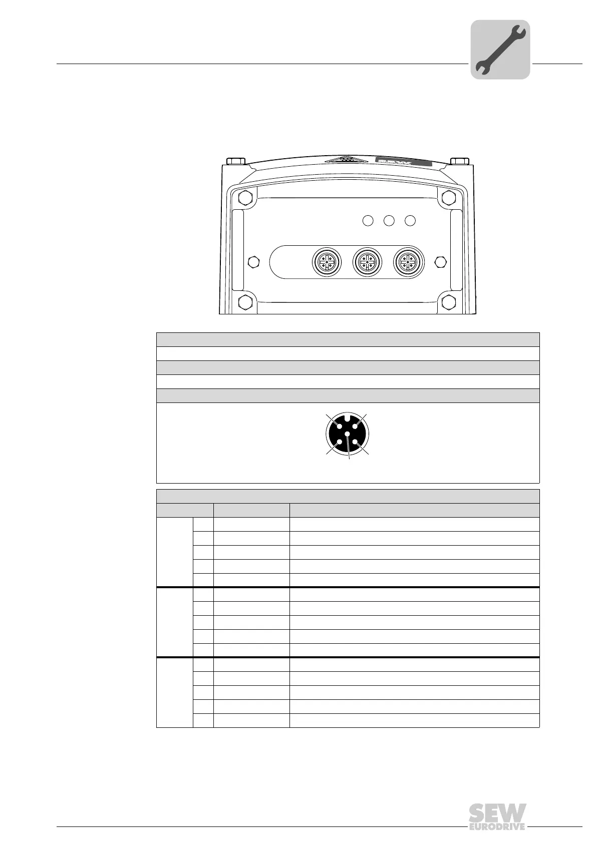
The following figure shows the M12 plug connectors of the GIO12B option:
9007201701475211
Function
Connection of I/Os
Connection type
M12, 5-pole, female, A-coded
Wiring diagram
2264816267
Assignment
No. Name Function
X3 1 +24V DC 24 V sensor supply
2 DI13 Binary input DI13 (switching signal)
3 0V24 0V24 reference potential for sensors
4 DI12 Binary input DI12 (switching signal)
5 res. Reserved
X2 1 +24V DC 24 V sensor supply
2 DI11 Binary input DI11 (switching signal)
3 0V24 0V24 reference potential for sensors
4 DI10 Binary input DI10 (switching signal)
5 res. Reserved
X1 1 +24V DC 24 V actuator supply
2 DO11 Binary output DO11 (switching signal)
3 0V24 0V24 reference potential for actuators
4 DIO10 Binary output DO10 (switching signal)
5 res. Reserved
X3 X2 X1X4
NET
RUN
DRIVE
1
4
3
2
5