72
Operating Instructions – Electronic Motor DRC.-..-SNI
5
Application options
Electrical Installation
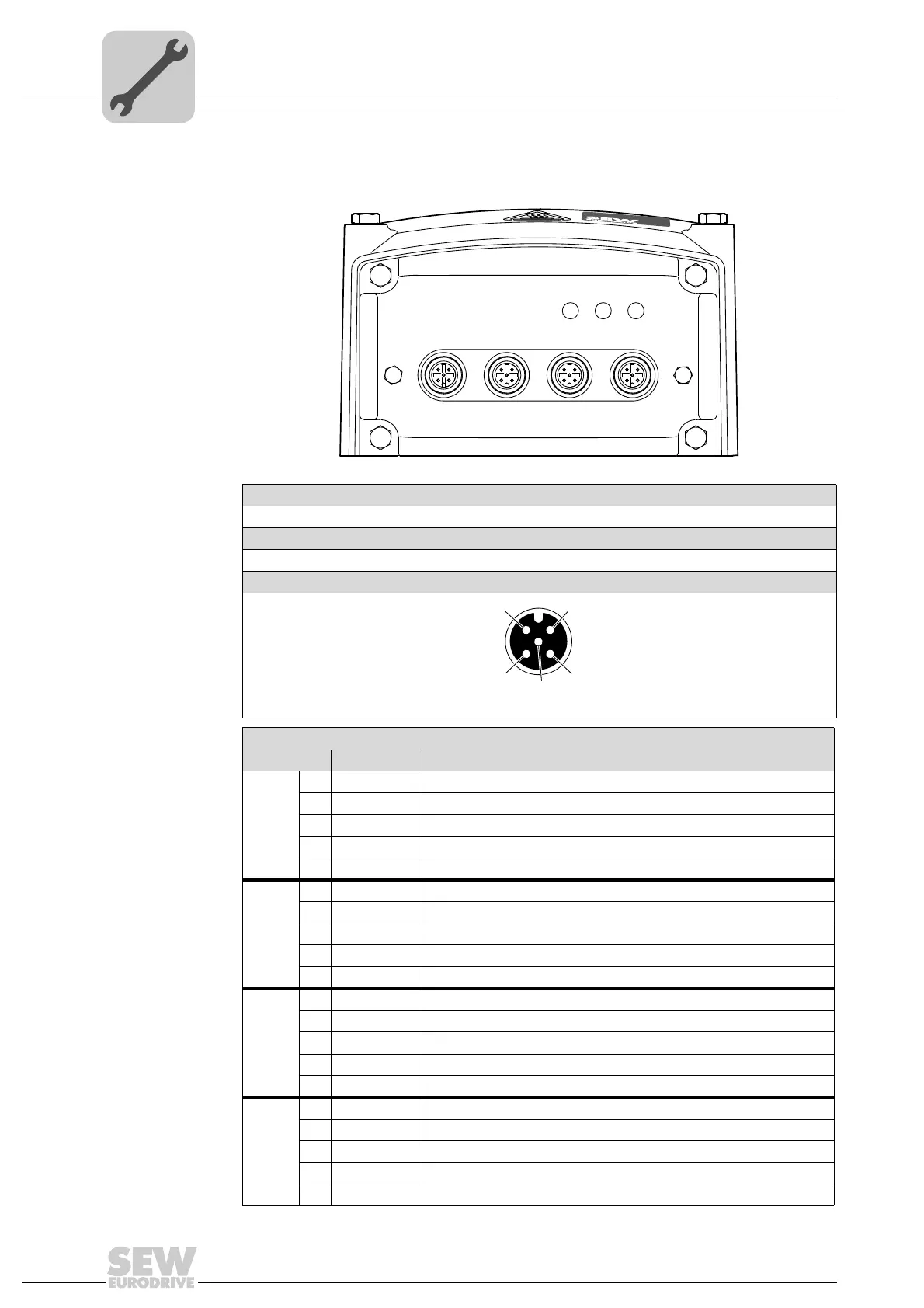
5.11.2 GIO13B
The following figure shows the M12 plug connectors of the GIO13B option:
9007201994722699
Function
Connection of I/Os
Connection type
M12, 5-pole, female, A-coded
Wiring diagram
2264816267
Assignment
No. Name Function
X4 1 AI10+ Analog input AI10+ Diff. input 1
2 AI10− Analog input AI10− Diff. input 2
3 0V24 0V24 reference potential for sensors
4 AO10 Analog output AO10 4 – 20 mA
5 res. Reserved
X3 1 +24V DC 24 V sensor supply
2 DI13 / LFI B Binary input DI13 / primary frequency (B)
3 0V24 0V24 reference potential for sensors
4 DI12 / LFI A Binary input DI12 / primary frequency (A)
5 res. Reserved
X2 1 +24V DC 24 V sensor supply
2 DI11 Binary input DI11
3 0V24 0V24 reference potential for sensors
4 DI10 Binary input DI10
5 res. Reserved
X1 1 DO10_A1 Relay contact (common)
2 DO10_A3 Relay contact (NC contact)
3 0V24 0V24 reference potential for actuators
4 DO10_A2 Relay contact (NO contact)
5 res. Reserved
X3 X2 X1X4
NET
RUN
DRIVE
1
4
3
2
5