106
Operating Instructions – Electronic Motor DRC.-..-SNI
8
Description of command PCB parameters
Parameters
8.4 Description of command PCB parameters
8.4.1 Display values
Command pcb parameters \ display values \ unit status
Operating status
index 8310.0
The parameter indicates the current operating state. The following operating states are
possible:
• READY
• NOT READY
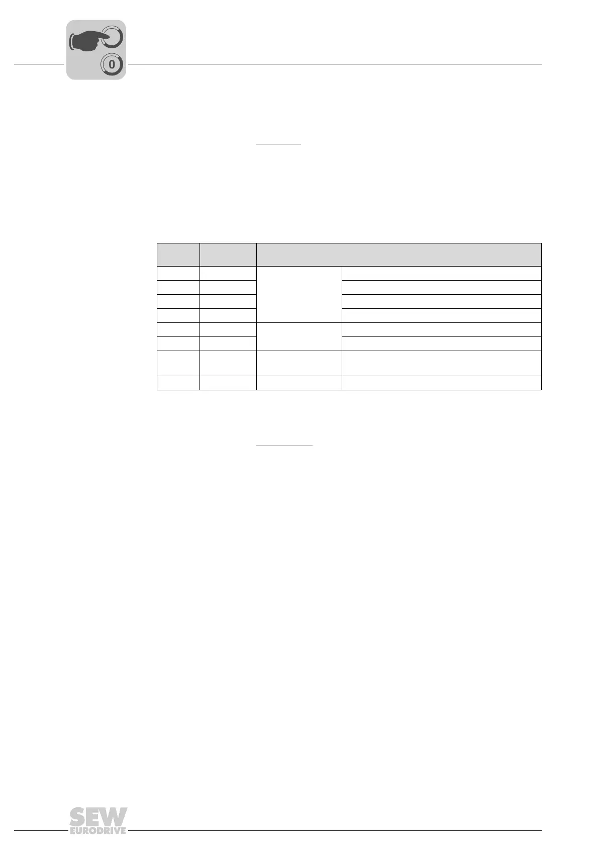
Setting of DIP
switch S1, S2
index 9621.10
The parameter indicates the setting of DIP switches S1 and S2:
Display of the DIP switch setting is independent of whether the DIP switch function is
activated or deactivated.
Command pcb parameters \ display values \ binary inputs
Binary input DI01
index 8334.0, bit 1
The parameter indicates the state of binary input DI01.
Binary input DI02
index 8334.0, bit 2
The parameter indicates the state of binary input DI02.
Binary input DI03
index 8334.0, bit 3
The parameter indicates the state of binary input DI03.
Binary input DI04
index 8334.0, bit 4
The parameter indicates the state of binary input DI04.
DIP
switch
Bit in index
9621.10
Functionality
S1/1 0 Unit address Unit address bit 2
0
S1/2 1 Unit address bit 2
1
S1/3 2 Unit address bit 2
2
S1/4 3 Unit address bit 2
3
S2/1 4 Binary coding operat-
ing mode
Operating mode bit 2
0
S2/2 5 Operating mode bit 2
1
S2/3 6 Use of the motion
control inputs
0: Sensors
1: Local mode
S2/4 7 res. Reserved