48
Operating Instructions – Electronic Motor DRC.-..-SNI
5
Terminal assignment
Electrical Installation
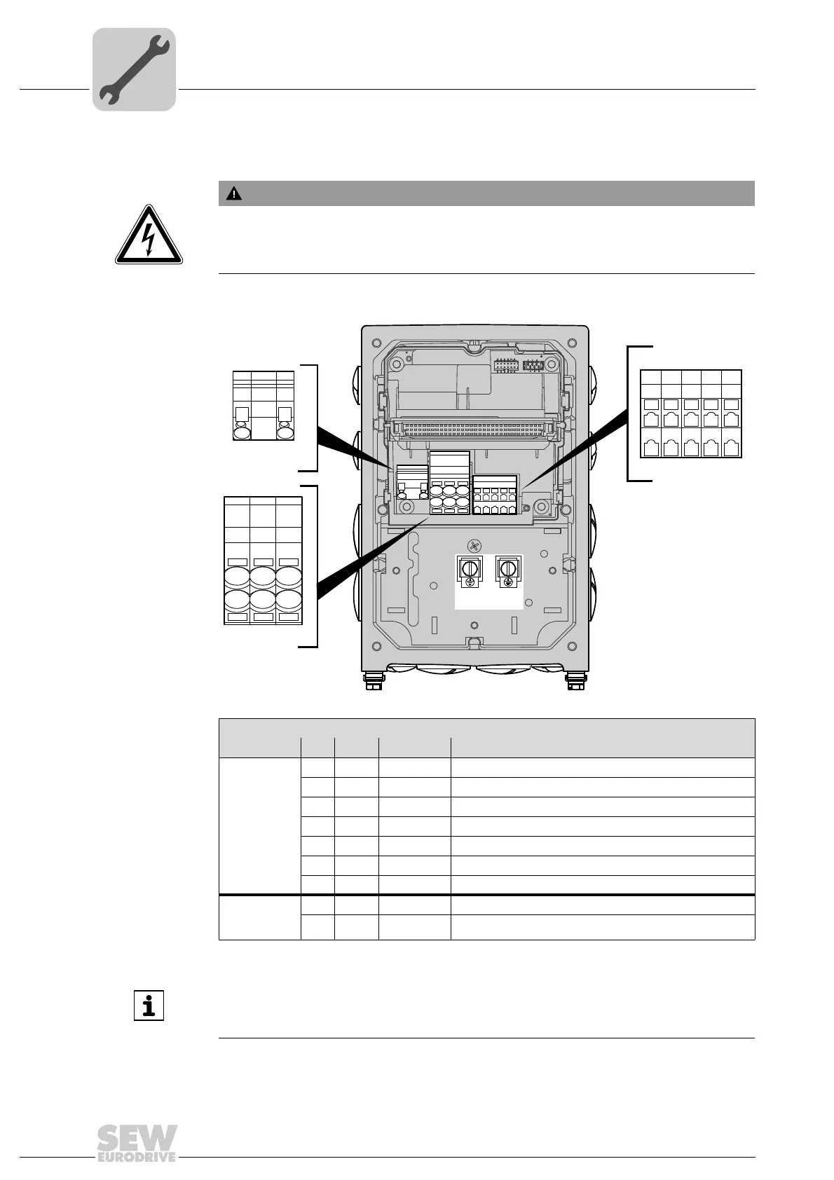
5.4 Terminal assignment
The following figure shows the terminal assignment of DRC-SNI:
WARNING
Electric shock due to regenerative operation when the shaft turns.
Severe or fatal injuries.
• Secure the output shaft against rotation when the electronics cover is removed.
4729233035
Assignment
Terminal No. Name Marking Function (permitted tightening torque)
X2 line
terminals
1L1 Brown Actuator supply phase L1 with SNI communication – IN
2L2 Black Actuator supply phase L2 with SNI communication – IN
3L3 Gray Actuator supply phase L3 with SNI communication – IN
11 L1 Brown Actuator supply phase L1 with SNI communication – OUT
12 L2 Black Actuator supply phase L2 with SNI communication – OUT
13 L3 Gray Actuator supply phase L3 with SNI communication – OUT
– PE – Protective earth connection (2.0 to 3.3 Nm )
X5 braking
resistor
terminals
1BW– Braking resistor connection
2BW– Braking resistor connection
PE
PE PE
PE
12 3
11 12 13
1
2
Braking resistor
terminals
Line terminals
X5
X2
12345
11 12 13 14 15
Control terminals
X7
12345
11 12 13 14 15
INFORMATION
The communication method requires that you must observe the order of the line
phases L1, L2, L3 between SNI controller and DRC-SNI 1 to 10.