Operating Instructions – Electronic Motor DRC.-..-SNI
49
5
Terminal assignment
Electrical Installation
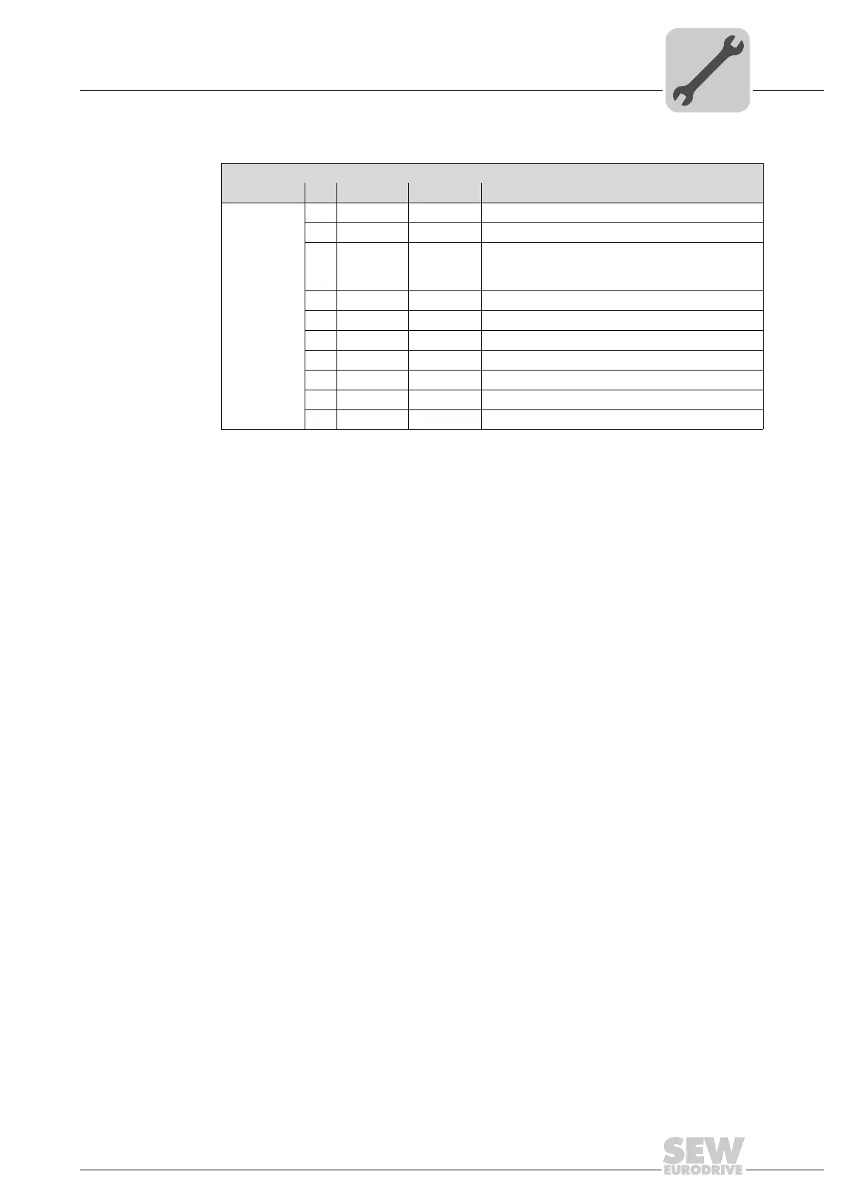
Assignment
Terminal No. Name Marking Function
X7 control
terminals
1STO + Yellow Input STO +
2STO − Yellow Input STO –
3 +24 V_SEN – Input for DC 24 V voltage supply for sensors
The sensor supply voltage is then available at the
optional plug connector
4 0V24_SEN – Input for 0V24 reference potential for sensors
5 24V_O – DC 24 V output
11 STO + Yellow Output STO + (to loop through)
12 STO − Yellow Output STO – (to loop through)
13 +24V_SEN – Looping of the DC 24 V voltage supply for sensors
14 0V24_SEN – Looping of the 0V24 reference potential for sensors
15 0V24_O – 0V24 reference potential output