50
Operating Instructions – Electronic Motor DRC.-..-SNI
5
Connecting DRC drive units
Electrical Installation
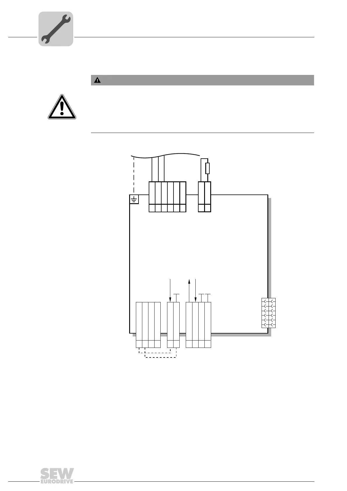
5.5 Connecting DRC drive units
WARNING
No safe disconnection of the DRC drive unit.
Severe or fatal injuries.
• Do not use the 24 V output (terminals 5, 15) for safety-related applications with
DRC drive units.
• You may only jumper the STO input with 24 V when the DRC drive unit need not
fulfill any safety function.
4729927435
[1] See documentation of the SNI controller
[2] See chapter "Terminal assignment"
[3] DC 24 V output
[4] Sensor supply input, the sensor supply voltage is then available at the optional plug
connector for sensor inputs
[5] Looping of the sensor supply input
[6] See chapter "Optional plug connector assignment"
[7] Braking resistor connection
2 STO IN
1 STO + IN
12 STO OUT
11 STO + OUT
15 0V24_O
5 24V_O
13 + 24V_SEN
3 + 24V_SEN
4 0V 24V_SEN
14 0V 24V_SEN
Control
terminals [2]
Line terminals [2]
Braking resistor
terminals [2]
[6] Connection the
optional
plug connector
X5132
for sensor inputs
[3] [4] [5]
L1 IN
1
L2 IN
2
BW
BW
DRC.-...-SNI
L3 IN
1
2
[7]
3
L1 OUT
11
L2 OUT12
L3 OUT
13
X2
X7
X5
[1] SNI controller connection